
Teknik Mesin (Mechanical Engineering) atau Teknik Mekanika adalah ilmu teknik dalam pengertian yang sangat luas - mempelajari tentang aplikasi dari prinsip dasar pengembangan ilmu Fisika untuk analisa, desain, manufaktur dan pemeliharaan sebuah sistem mekanika. Ilmu ini membutuhkan pengertian mendalam atas konsep utama dari cabang ilmu mekanika, kinematika, termodinamika dan energi. Seorang ahli dari Teknik Mesin disebut sebagai insinyur Teknik Mesin, yang memanfaatkan pengertian atas ilmu teknik ini dalam mendesain dan menganalisa pembuatan kendaraan, pesawat terbang, pabrik industri, peralatan dan mesin industri dan bidang lainnya yang berkembang dari Teknik Mesin. teknik mesin terdiri dari :
- Konversi Energi (Energy Conversion)
- Perancangan Mesin (Mechanical Design)
- Ilmu dan Teknik Material (Material Science and Engineering)
- Teknik Produksi Mesin (Mechanical Production Engineering)
Mechanical engineering is a discipline of engineering that applies the principles of physics and materials science for analysis, design, manufacturing, and maintenance of mechanical systems. It is the branch of engineering that involves the production and usage of heat and mechanical power for the design, production, and operation of machines and tools. It is one of the oldest and broadest engineering disciplines.
The engineering field requires an understanding of core concepts including mechanics, kinematics, thermodynamics, materials science, and structural analysis. Mechanical engineers use these core principles along with tools like computer-aided engineering and product lifecycle management to design and analyze manufacturing plants, industrial equipment and machinery, heating and cooling systems, transport systems, aircraft, watercraft, robotics, medical devices and more.
Mechanical engineering emerged as a field during the industrial revolution in Europe in the 18th century; however, its development can be traced back several thousand years around the world. Mechanical engineering science emerged in the 19th century as a result of developments in the field of physics. The field has continually evolved to incorporate advancements in technology, and mechanical engineers today are pursuing developments in such fields as composites, mechatronics, and nanotechnology. Mechanical engineering overlaps with aerospace engineering, civil engineering, electrical engineering, petroleum engineering, and chemical engineering to varying amounts.
Development
Applications of mechanical engineering are found in the records of many ancient and medieval societies throughout the globe. In ancient Greece, the works of Archimedes (287 BC–212 BC) deeply influenced mechanics in the Western tradition and Heron of Alexandria (c. 10–70 AD) created the first steam engine. In China, Zhang Heng (78–139 AD) improved a water clock and invented a seismometer, and Ma Jun (200–265 AD) invented a chariot with differential gears. The medieval Chinese horologist and engineer Su Song (1020–1101 AD) incorporated an escapement mechanism into his astronomical clock tower two centuries before any escapement can be found in clocks of medieval Europe, as well as the world's first known endless power-transmitting chain drive.
During the years from 7th to 15th century, the era called the Islamic Golden Age, there were remarkable contributions from Muslim inventors in the field of mechanical technology. Al-Jazari, who was one of them, wrote his famous Book of Knowledge of Ingenious Mechanical Devices in 1206, and presented many mechanical designs. He is also considered to be the inventor of such mechanical devices which now form the very basic of mechanisms, such as the crankshaft and camshaft.
Important breakthroughs in the foundations of mechanical engineering occurred in England during the 17th century when Sir Isaac Newton both formulated the three Newton's Laws of Motion and developed calculus. Newton was reluctant to publish his methods and laws for years, but he was finally persuaded to do so by his colleagues, such as Sir Edmund Halley, much to the benefit of all mankind.
During the early 19th century in England, Germany and Scotland, the development of machine tools led mechanical engineering to develop as a separate field within engineering, providing manufacturing machines and the engines to power them. The first British professional society of mechanical engineers was formed in 1847 Institution of Mechanical Engineers, thirty years after the civil engineers formed the first such professional society Institution of Civil Engineers. On the European continent, Johann Von Zimmermann (1820–1901) founded the first factory for grinding machines in Chemnitz (Germany) in 1848.
In the United States, the American Society of Mechanical Engineers (ASME) was formed in 1880, becoming the third such professional engineering society, after the American Society of Civil Engineers (1852) and the American Institute of Mining Engineers (1871). The first schools in the United States to offer an engineering education were the United States Military Academy in 1817, an institution now known as Norwich University in 1819, and Rensselaer Polytechnic Institute in 1825. Education in mechanical engineering has historically been based on a strong foundation in mathematics and science.
Education
Degrees in mechanical engineering are offered at universities worldwide. In Brazil, Ireland, China, Greece, Turkey, North America, South Asia, India and the United Kingdom, mechanical engineering programs typically take four to five years of study and result in a Bachelor of Science (B.Sc), Bachelor of Science Engineering (B.ScEng), Bachelor of Engineering (B.Eng), Bachelor of Technology (B.Tech), or Bachelor of Applied Science (B.A.Sc) degree, in or with emphasis in mechanical engineering. In Spain, Portugal and most of South America, where neither BSc nor BTech programs have been adopted, the formal name for the degree is "Mechanical Engineer", and the course work is based on five or six years of training. In Italy the course work is based on five years of training, but in order to qualify as an Engineer you have to pass a state exam at the end of the course.
In Australia, mechanical engineering degrees are awarded as Bachelor of Engineering (Mechanical). The degree takes four years of full time study to achieve. To ensure quality in engineering degrees, the Australian Institution of Engineers accredits engineering degrees awarded by Australian universities. Before the degree can be awarded, the student must complete at least 3 months of on the job work experience in an engineering firm.
In the United States, most undergraduate mechanical engineering programs are accredited by the Accreditation Board for Engineering and Technology (ABET) to ensure similar course requirements and standards among universities. The ABET web site lists 276 accredited mechanical engineering programs as of June 19, 2006. Mechanical engineering programs in Canada are accredited by the Canadian Engineering Accreditation Board (CEAB), and most other countries offering engineering degrees have similar accreditation societies.
Some mechanical engineers go on to pursue a postgraduate degree such as a Master of Engineering (M.Eng.), Master of Technology, Master of Science (M.Sc.), Master of Engineering Management (M.E.M), a Doctor of Philosophy in engineering (Eng.D., Ph.D) or an engineer's degree. The master's and engineer's degrees may or may not include research. The Doctor of Philosophy includes a significant research component and is often viewed as the entry point to academia. The Engineer's degree exists at a few institutions at an intermediate level between the master's degree and the doctorate.
Coursework
Standards set by each country's accreditation society are intended to provide uniformity in fundamental subject material, promote competence among graduating engineers, and to maintain confidence in the engineering profession as a whole. Engineering programs in the U.S., for example, are required by ABET to show that their students can "work professionally in both thermal and mechanical systems areas. "The specific courses required to graduate, however, may differ from program to program. Universities and Institutes of technology will often combine multiple subjects into a single class or split a subject into multiple classes, depending on the faculty available and the university's major area(s) of research.
The fundamental subjects of mechanical engineering usually include:
- Statics and Dynamics
- Strength of materials and Solid mechanics
- Instrumentation and Measurement
- Electrotechnology
- Electronics
- Thermodynamics, Heat transfer, Energy conversion, and HVAC (Heating, Ventilation, and Air Conditioning)
- Combustion, Automotive engines, Fuels
- Fluid mechanics and Fluid dynamics
- Mechanism design (including kinematics and dynamics)
- Manufacturing engineering, technology, or processes
- Hydraulics and pneumatics
- Mathematics - in particular, calculus, differential equations, and linear algebra.
- Engineering design
- Product design
- Mechatronics and control theory
- Material Engineering
- Design engineering, Drafting, computer-aided design (CAD) (including solid modeling), and computer-aided manufacturing (CAM)
Mechanical engineers are also expected to understand and be able to apply basic concepts from chemistry, physics, chemical engineering, civil engineering, and electrical engineering. Most mechanical engineering programs include multiple semesters of calculus, as well as advanced mathematical concepts including differential equations, partial differential equations, linear algebra, abstract algebra, and differential geometry, among others.
In addition to the core mechanical engineering curriculum, many mechanical engineering programs offer more specialized programs and classes, such as robotics, transport and logistics, cryogenics, fuel technology, automotive engineering, biomechanics, vibration, optics and others, if a separate department does not exist for these subjects.
Most mechanical engineering programs also require varying amounts of research or community projects to gain practical problem-solving experience. In the United States it is common for mechanical engineering students to complete one or more internships while studying, though this is not typically mandated by the university. Cooperative education is another option.
License
Engineers may seek license by a state, provincial, or national government. The purpose of this process is to ensure that engineers possess the necessary technical knowledge, real-world experience, and knowledge of the local legal system to practice engineering at a professional level. Once certified, the engineer is given the title of Professional Engineer (in the United States, Canada, Japan, South Korea, Bangladesh and South Africa), Chartered Engineer (in the United Kingdom, Ireland, India and Zimbabwe), Chartered Professional Engineer (in Australia and New Zealand) or European Engineer (much of the European Union). Not all mechanical engineers choose to become licensed; those that do can be distinguished as Chartered or Professional Engineers by the post-nominal title P.E., P.Eng., or C.Eng., as in: Mike Thompson, P.Eng.
In the U.S., to become a licensed Professional Engineer, an engineer must pass the comprehensive FE (Fundamentals of Engineering) exam, work a given number of years as an Engineering Intern (EI) or Engineer-in-Training (EIT), and finally pass the "Principles and Practice" or PE (Practicing Engineer or Professional Engineer) exams.
In the United States, the requirements and steps of this process are set forth by the National Council of Examiners for Engineering and Surveying (NCEES), a national non-profit representing all states. In the UK, current graduates require a B.Eng. plus an appropriate masters degree or an integrated M.Eng. degree, a minimum of 4 years post graduate on the job competency development, and a peer reviewed project report in the candidates specialty area in order to become chartered through the Institution of Mechanical Engineers.
In most modern countries, certain engineering tasks, such as the design of bridges, electric power plants, and chemical plants, must be approved by a Professional Engineer or a Chartered Engineer. "Only a licensed engineer, for instance, may prepare, sign, seal and submit engineering plans and drawings to a public authority for approval, or to seal engineering work for public and private clients." This requirement can be written into state and provincial legislation, such as in the Canadian provinces, for example the Ontario or Quebec's Engineer Act.
In other countries, such as Australia, no such legislation exists; however, practically all certifying bodies maintain a code of ethics independent of legislation that they expect all members to abide by or risk expulsion.
Salaries and workforce statistics
The total number of engineers employed in the U.S. in 2009 was roughly 1.6 million. Of these, 239,000 were mechanical engineers (14.9%), the second largest discipline by size behind civil (278,000). The total number of mechanical engineering jobs in 2009 was projected to grow 6% over the next decade, with average starting salaries being $58,800 with a bachelor's degree. The median annual income of mechanical engineers in the U.S. workforce was roughly $74,900. This number was highest when working for the government ($86,250), and lowest in education ($63,050).
In 2007, Canadian engineers made an average of CAD$29.83 per hour with 4% unemployed. The average for all occupations was $18.07 per hour with 7% unemployed. Twelve percent of these engineers were self-employed, and since 1997 the proportion of female engineers had risen to 6%.
Modern tools
Many mechanical engineering companies, especially those in industrialized nations, have begun to incorporate Computer-Aided Engineering (CAE) programs into their existing design and analysis processes, including 2D and 3D Solid Modeling computer-aided design (CAD). This method has many benefits, including easier and more exhaustive visualization of products, the ability to create virtual assemblies of parts, and the ease of use in designing mating interfaces and tolerances.
 |
| An oblique view of a four-cylinder inline crankshaft with pistons |
Other CAE programs commonly used by mechanical engineers include product lifecycle management (PLM) tools and analysis tools used to perform complex simulations. Analysis tools may be used to predict product response to expected loads, including fatigue life and manufacturability. These tools include finite element analysis (FEA), computational fluid dynamics (CFD), and Computer-Aided Manufacturing (CAM).
Using CAE programs, a mechanical design team can quickly and cheaply iterate the design process to develop a product that better meets cost, performance, and other constraints. No physical prototype need be created until the design nears completion, allowing hundreds or thousands of designs to be evaluated, instead of a relative few. In addition, CAE analysis programs can model complicated physical phenomena which cannot be solved by hand, such as viscoelasticity, complex contact between mating parts, or non-Newtonian flows.
As mechanical engineering begins to merge with other disciplines, as seen in mechatronics, Multidisciplinary Design Optimization (MDO) is being used with other CAE programs to automate and improve the iterative design process. MDO tools wrap around existing CAE processes, allowing product evaluation to continue even after the analyst goes home for the day. They also utilize sophisticated optimization algorithms to more intelligently explore possible designs, often finding better, innovative solutions to difficult multidisciplinary design problems.
Subdisciplines
The field of mechanical engineering can be thought of as a collection of many mechanical engineering science disciplines. Several of these subdisciplines which are typically taught at the undergraduate level are listed below, with a brief explanation and the most common application of each. Some of these subdisciplines are unique to mechanical engineering, while others are a combination of mechanical engineering and one or more other disciplines. Most work that a mechanical engineer does uses skills and techniques from several of these subdisciplines, as well as specialized subdisciplines. Specialized subdisciplines, as used in this article, are more likely to be the subject of graduate studies or on-the-job training than undergraduate research. Several specialized subdisciplines are discussed in this section.
Mechanics
 |
| Mohr's circle, a common tool to study stresses in a mechanical element |
Mechanics is, in the most general sense, the study of forces and their effect upon matter. Typically, engineering mechanics is used to analyze and predict the acceleration and deformation (both elastic and plastic) of objects under known forces (also called loads) or stresses. Subdisciplines of mechanics include
- Statics, the study of non-moving bodies under known loads, how forces affect static bodies
- Dynamics (or kinetics), the study of how forces affect moving bodies
- Mechanics of materials, the study of how different materials deform under various types of stress
- Fluid mechanics, the study of how fluids react to forces
- Continuum mechanics, a method of applying mechanics that assumes that objects are continuous (rather than discrete)
Mechanical engineers typically use mechanics in the design or analysis phases of engineering. If the engineering project were the design of a vehicle, statics might be employed to design the frame of the vehicle, in order to evaluate where the stresses will be most intense. Dynamics might be used when designing the car's engine, to evaluate the forces in the pistons and cams as the engine cycles. Mechanics of materials might be used to choose appropriate materials for the frame and engine. Fluid mechanics might be used to design a ventilation system for the vehicle (see HVAC), or to design the intake system for the engine.
Kinematics
Kinematics is the study of the motion of bodies (objects) and systems (groups of objects), while ignoring the forces that cause the motion. The movement of a crane and the oscillations of a piston in an engine are both simple kinematic systems. The crane is a type of open kinematic chain, while the piston is part of a closed four-bar linkage.
Mechanical engineers typically use kinematics in the design and analysis of mechanisms. Kinematics can be used to find the possible range of motion for a given mechanism, or, working in reverse, can be used to design a mechanism that has a desired range of motion.
Mechatronics and robotics
 |
| Training FMS with learning robot SCORBOT-ER 4u,workbench CNC Mill & CNC Lathe |
Mechatronics is an interdisciplinary branch of mechanical engineering, electrical engineering and software engineering that is concerned with integrating electrical and mechanical engineering to create hybrid systems. In this way, machines can be automated through the use of electric motors, servo-mechanisms, and other electrical systems in conjunction with special software. A common example of a mechatronics system is a CD-ROM drive. Mechanical systems open and close the drive, spin the CD and move the laser, while an optical system reads the data on the CD and converts it to bits. Integrated software controls the process and communicates the contents of the CD to the computer.
Robotics is the application of mechatronics to create robots, which are often used in industry to perform tasks that are dangerous, unpleasant, or repetitive. These robots may be of any shape and size, but all are preprogrammed and interact physically with the world. To create a robot, an engineer typically employs kinematics (to determine the robot's range of motion) and mechanics (to determine the stresses within the robot).
Robots are used extensively in industrial engineering. They allow businesses to save money on labor, perform tasks that are either too dangerous or too precise for humans to perform them economically, and to insure better quality. Many companies employ assembly lines of robots,especially in Automotive Industries and some factories are so robotized that they can run by themselves. Outside the factory, robots have been employed in bomb disposal, space exploration, and many other fields. Robots are also sold for various residential applications.
Structural analysis
Structural analysis is the branch of mechanical engineering (and also civil engineering) devoted to examining why and how objects fail and to fix the objects and their performance. Structural failures occur in two general modes: static failure, and fatigue failure. Static structural failure occurs when, upon being loaded (having a force applied) the object being analyzed either breaks or is deformed plastically, depending on the criterion for failure. Fatigue failure occurs when an object fails after a number of repeated loading and unloading cycles. Fatigue failure occurs because of imperfections in the object: a microscopic crack on the surface of the object, for instance, will grow slightly with each cycle (propagation) until the crack is large enough to cause ultimate failure.
Failure is not simply defined as when a part breaks, however; it is defined as when a part does not operate as intended. Some systems, such as the perforated top sections of some plastic bags, are designed to break. If these systems do not break, failure analysis might be employed to determine the cause.
Structural analysis is often used by mechanical engineers after a failure has occurred, or when designing to prevent failure. Engineers often use online documents and books such as those published by ASM to aid them in determining the type of failure and possible causes.
Structural analysis may be used in the office when designing parts, in the field to analyze failed parts, or in laboratories where parts might undergo controlled failure tests.
Thermodynamics and thermo-science
Thermodynamics is an applied science used in several branches of engineering, including mechanical and chemical engineering. At its simplest, thermodynamics is the study of energy, its use and transformation through a system. Typically, engineering thermodynamics is concerned with changing energy from one form to another. As an example, automotive engines convert chemical energy (enthalpy) from the fuel into heat, and then into mechanical work that eventually turns the wheels.
Thermodynamics principles are used by mechanical engineers in the fields of heat transfer, thermofluids, and energy conversion. Mechanical engineers use thermo-science to design engines and power plants, heating, ventilation, and air-conditioning (HVAC) systems, heat exchangers, heat sinks, radiators, refrigeration, insulation, and others.
Design and Drafting
 |
| A CAD model of a mechanical double seal |
Drafting or technical drawing is the means by which mechanical engineers design products and create instructions for manufacturing parts. A technical drawing can be a computer model or hand-drawn schematic showing all the dimensions necessary to manufacture a part, as well as assembly notes, a list of required materials, and other pertinent information. A U.S. mechanical engineer or skilled worker who creates technical drawings may be referred to as a drafter or draftsman. Drafting has historically been a two-dimensional process, but Computer-Aided Design (CAD) programs now allow the designer to create in three dimensions.
Instructions for manufacturing a part must be fed to the necessary machinery, either manually, through programmed instructions, or through the use of a Computer-Aided Manufacturing (CAM) or combined CAD/CAM program. Optionally, an engineer may also manually manufacture a part using the technical drawings, but this is becoming an increasing rarity, with the advent of Computer Numerically Controlled (CNC) manufacturing. Engineers primarily manually manufacture parts in the areas of applied spray coatings, finishes, and other processes that cannot economically or practically be done by a machine.
Drafting is used in nearly every subdiscipline of mechanical engineering, and by many other branches of engineering and architecture. Three-dimensional models created using CAD software are also commonly used in Finite Element Analysis (FEA) and Computational Fluid Dynamics (CFD).
Frontiers of research
Mechanical engineers are constantly pushing the boundaries of what is physically possible in order to produce safer, cheaper, and more efficient machines and mechanical systems. Some technologies at the cutting edge of mechanical engineering are listed below (see also exploratory engineering).
Micro electro-mechanical systems (MEMS)
Micron-scale mechanical components such as springs, gears, fluidic and heat transfer devices are fabricated from a variety of substrate materials such as silicon, glass and polymers like SU8. Examples of MEMS components will be the accelerometers that are used as car airbag sensors, modern cell phones, gyroscopes for precise positioning and microfluidic devices used in biomedical applications.
Friction stir welding (FSW)
Friction stir welding, a new type of welding, was discovered in 1991 by The Welding Institute (TWI). This innovative steady state (non-fusion) welding technique joins materials previously un-weldable, including several aluminum alloys. It may play an important role in the future construction of airplanes, potentially replacing rivets. Current uses of this technology to date include welding the seams of the aluminum main Space Shuttle external tank, Orion Crew Vehicle test article, Boeing Delta II and Delta IV Expendable Launch Vehicles and the SpaceX Falcon 1 rocket, armor plating for amphibious assault ships, and welding the wings and fuselage panels of the new Eclipse 500 aircraft from Eclipse Aviation among an increasingly growing pool of uses.
Friction-stir welding (FSW) is a solid-state joining process (meaning the metal is not melted during the process) and is used for applications where the original metal characteristics must remain unchanged as far as possible. This process is primarily used on aluminium, and most often on large pieces which cannot be easily heat treated post weld to recover temper characteristics.
It was invented and experimentally proven by Wayne Thomas and a team of his colleagues at The Welding Institute UK in December 1991. TWI holds a number of patents on the process, the first being the most descriptive.
 |
| Close-up view of a friction stir weld tack tool. |
 |
| The bulkhead and nosecone of the Orion spacecraft are joined using friction stir welding. |
Friction-stir welding (FSW) is a solid-state joining process (meaning the metal is not melted during the process) and is used for applications where the original metal characteristics must remain unchanged as far as possible. This process is primarily used on aluminium, and most often on large pieces which cannot be easily heat treated post weld to recover temper characteristics.
It was invented and experimentally proven by Wayne Thomas and a team of his colleagues at The Welding Institute UK in December 1991. TWI holds a number of patents on the process, the first being the most descriptive.
Principle of operation
 |
| Schematic diagram of the FSW process: (A) Two discrete metal workpieces butted together, along with the tool (with a probe |
In FSW, a cylindrical-shouldered tool, with a profiled threaded/unthreaded probe (nib or pin) is rotated at a constant speed and fed at a constant traverse rate into the joint line between two pieces of sheet or plate material, which are butted together. The parts have to be clamped rigidly onto a backing bar in a manner that prevents the abutting joint faces from being forced apart. The length of the nib is slightly less than the weld depth required and the tool shoulder should be in intimate contact with the work surface. The nib is then moved against the work, or vice versa.
Frictional heat is generated between the wear-resistant welding tool shoulder and nib, and the material of the work pieces. This heat, along with the heat generated by the mechanical mixing process and the adiabatic heat within the material, cause the stirred materials to soften without reaching the melting point (hence cited a solid-state process), allowing the traversing of the tool along the weld line in a plasticised tubular shaft of metal. As the pin is moved in the direction of welding, the leading face of the pin, assisted by a special pin profile, forces plasticised material to the back of the pin while applying a substantial forging force to consolidate the weld metal. The welding of the material is facilitated by severe plastic deformation in the solid state, involving dynamic recrystallization of the base material.
Microstructural features
 |
| (B) The progress of the tool through the joint, also showing the weld zone and the region affected by the tool shoulder. |
The solid-state nature of the FSW process, combined with its unusual tool and asymmetric nature, results in a highly characteristic microstructure. The microstructure can be broken up into the following zones:
- The stir zone (also nugget, dynamically recrystallised zone) is a region of heavily deformed material that roughly corresponds to the location of the pin during welding. The grains within the stir zone are roughly equiaxed and often an order of magnitude smaller than the grains in the parent material. A unique feature of the stir zone is the common occurrence of several concentric rings which has been referred to as an "onion-ring" structure. The precise origin of these rings has not been firmly established, although variations in particle number density, grain size and texture have all been suggested.
- The flow arm zone is on the upper surface of the weld and consists of material that is dragged by the shoulder from the retreating side of the weld, around the rear of the tool, and deposited on the advancing side.
- The thermo-mechanically affected zone (TMAZ) occurs on either side of the stir zone. In this region the strain and temperature are lower and the effect of welding on the microstructure is correspondingly smaller. Unlike the stir zone the microstructure is recognizably that of the parent material, albeit significantly deformed and rotated. Although the term TMAZ technically refers to the entire deformed region it is often used to describe any region not already covered by the terms stir zone and flow arm.
- The Heat-Affected Zone (HAZ) is common to all welding processes. As indicated by the name, this region is subjected to a thermal cycle but is not deformed during welding. The temperatures are lower than those in the TMAZ but may still have a significant effect if the microstructure is thermally unstable. In fact, in age-hardened aluminium alloys this region commonly exhibits the poorest mechanical properties.
Advantages and disadvantages
The solid-state nature of FSW immediately leads to several advantages over fusion welding methods since any problems associated with cooling from the liquid phase are immediately avoided. Issues such as porosity, solute redistribution, solidification cracking and liquation cracking are not an issue during FSW. In general, FSW has been found to produce a low concentration of defects and is very tolerant to variations in parameters and materials.
Nevertheless, FSW is associated with a number of unique defects. Insufficient weld temperatures, due to low rotational speeds or high traverse speeds, for example, mean that the weld material is unable to accommodate the extensive deformation during welding. This may result in long, tunnel-like defects running along the weld which may occur on the surface or subsurface. Low temperatures may also limit the forging action of the tool and so reduce the continuity of the bond between the material from each side of the weld. The light contact between the material has given rise to the name "kissing-bond". This defect is particularly worrying since it is very difficult to detect using nondestructive methods such as X-ray or ultrasonic testing. If the pin is not long enough or the tool rises out of the plate then the interface at the bottom of the weld may not be disrupted and forged by the tool, resulting in a lack-of-penetration defect. This is essentially a notch in the material which can be a potent source of fatigue cracks.
A number of potential advantages of FSW over conventional fusion-welding processes have been identified:
- Good mechanical properties in the as welded condition
- Improved safety due to the absence of toxic fumes or the spatter of molten material.
- No consumables — A threaded pin made of conventional tool steel, e.g., hardened H13, can weld over 1000m of aluminium, and no filler or gas shield is required for aluminium.
- Easily automated on simple milling machines — lower setup costs and less training.
- Can operate in all positions (horizontal, vertical, etc.), as there is no weld pool.
- Generally good weld appearance and minimal thickness under/over-matching, thus reducing the need for expensive machining after welding.
- Low environmental impact.
However, some disadvantages of the process have been identified:
- Exit hole left when tool is withdrawn.
- Large down forces required with heavy-duty clamping necessary to hold the plates together.
- Less flexible than manual and arc processes (difficulties with thickness variations and non-linear welds).
- Often slower traverse rate than some fusion welding techniques, although this may be offset if fewer welding passes are required.
Important welding parameters
Tool rotation and traverse speeds
There are two tool speeds to be considered in friction-stir welding; how fast the tool rotates and how quickly it traverses the interface. These two parameters have considerable importance and must be chosen with care to ensure a successful and efficient welding cycle. The relationship between the welding speeds and the heat input during welding is complex but, in general, it can be said that increasing the rotation speed or decreasing the traverse speed will result in a hotter weld. In order to produce a successful weld it is necessary that the material surrounding the tool is hot enough to enable the extensive plastic flow required and minimise the forces acting on the tool. If the material is too cold then voids or other flaws may be present in the stir zone and in extreme cases the tool may break.
Excessively high heat input, on the other hand may be detrimental to the final properties of the weld. Theoretically, this could even result in defects due to the liquation of low-melting-point phases (similar to liquation cracking in fusion welds). These competing demands lead onto the concept of a "processing window": the range of processing parameters viz. tool rotation and traverse speed, that will produce a good quality weld. Within this window the resulting weld will have a sufficiently high heat input to ensure adequate material plasticity but not so high that the weld properties are excessively deteriorated.
Tool tilt and plunge depth
 |
| A drawing showing the plunge depth and tilt of the tool. The tool is moving to the left. |
The plunge depth is defined as the depth of the lowest point of the shoulder below the surface of the welded plate and has been found to be a critical parameter for ensuring weld quality. Plunging the shoulder below the plate surface increases the pressure below the tool and helps ensure adequate forging of the material at the rear of the tool. Tilting the tool by 2-4 degrees, such that the rear of the tool is lower than the front, has been found to assist this forging process. The plunge depth needs to be correctly set, both to ensure the necessary downward pressure is achieved and to ensure that the tool fully penetrates the weld. Given the high loads required the welding machine may deflect and so reduce the plunge depth compared to the nominal setting, which may result in flaws in the weld. On the other hand an excessive plunge depth may result in the pin rubbing on the backing plate surface or a significant undermatch of the weld thickness compared to the base material. Variable load welders have been developed to automatically compensate for changes in the tool displacement while TWI have demonstrated a roller system that maintains the tool position above the weld plate.
Tool design
The design of the toos is a critical factor as a good tool can improve both the quality of the weld and the maximum possible welding speed. It is desirable that the tool material is sufficiently strong, tough and hard wearing, at the welding temperature. Further it should have a good oxidation resistance and a low thermal conductivity to minimise heat loss and thermal damage to the machinery further up the drive train. Hot-worked tool steel such as AISI H13 has proven perfectly acceptable for welding aluminium alloys within thickness ranges of 0.5 – 50 mm but more advanced tool materials are necessary for more demanding applications such as highly abrasive metal matrix composites or higher melting point materials such as steel or titanium.
Improvements in tool design have been shown to cause substantial improvements in productivity and quality. TWI has developed tools specifically designed to increase the depth of penetration and so increase the plate thickness that can be successfully welded. An example is the "whorl" design that uses a tapered pin with re-entrant features or a variable pitch thread in order to improve the downwards flow of material. Additional designs include the Triflute and Trivex series. The Triflute design has a complex system of three tapering, threaded re-entrant flutes that appear to increase material movement around the tool. The Trivex tools use a simpler, non-cylindrical, pin and have been found to reduce the forces acting on the tool during welding.
The majority of tools have a concave shoulder profile which acts as an escape volume for the material displaced by the pin, prevents material from extruding out of the sides of the shoulder and maintains downwards pressure and hence good forging of the material behind the tool. The Triflute tool uses an alternative system with a series of concentric grooves machined into the surface which are intended to produce additional movement of material in the upper layers of the weld.
Welding forces
During welding a number of forces will act on the tool:
- A downwards force is necessary to maintain the position of the tool at or below the material surface. Some friction-stir welding machines operate under load control but in many cases the vertical position of the tool is preset and so the load will vary during welding.
- The traverse force acts parallel to the tool motion and is positive in the traverse direction. Since this force arises as a result of the resistance of the material to the motion of the tool it might be expected that this force will decrease as the temperature of the material around the tool is increased.
- The lateral force may act perpendicular to the tool traverse direction and is defined here as positive towards the advancing side of the weld.
- Torque is required to rotate the tool, the amount of which will depend on the down force and friction coefficient (sliding friction) and/or the flow strength of the material in the surrounding region (sticking friction).
In order to prevent tool fracture and to minimize excessive wear and tear on the tool and associated machinery, the welding cycle should be modified so that the forces acting on the tool are as low as possible, and abrupt changes are avoided. In order to find the best combination of welding parameters it is likely that a compromise must be reached, since the conditions that favour low forces (e.g. high heat input, low travel speeds) may be undesirable from the point of view of productivity and weld properties.
Flow of material
Early work on the mode of material flow around the tool used inserts of a different alloy, which had a different contrast to the normal material when viewed through a microscope, in an effort to determine where material was moved as the tool passed. The data was interpreted as representing a form of in-situ extrusion where the tool, backing plate and cold base material form the "extrusion chamber" through which the hot, plasticised material is forced. In this model the rotation of the tool draws little or no material around the front of the pin instead the material parts in front of the pin and passes down either side. After the material has passed the pin the side pressure exerted by the "die" forces the material back together and consolidation of the join occurs as the rear of the tool shoulder passes overhead and the large down force forges the material.
More recently, an alternative theory has been advanced that advocates considerable material movement in certain locations. This theory holds that some material does rotate around the pin, for at least one rotation, and it is this material movement that produces the "onion-ring" structure in the stir zone. The researchers used a combination of thin Cu strip inserts and a "frozen pin" technique, where the tool is rapidly stopped in place. They suggested that material motion occurs by two processes:
- Material on the advancing front side of a weld enters into a zone that rotates and advances with the pin. This material was very highly deformed and sloughs off behind the pin to form arc-shaped features when viewed from above (i.e. down the tool axis). It was noted that the copper entered the rotational zone around the pin, where it was broken up into fragments. These fragments were only found in the arc shaped features of material behind the tool.
- The lighter material came from the retreating front side of the pin and was dragged around to the rear of the tool and filled in the gaps between the arcs of advancing side material. This material did not rotate around the pin and the lower level of deformation resulted in a larger grain size.
Generation and flow of heat
For any welding process it is, in general, desirable to increase the travel speed and minimise the heat input as this will increase productivity and possibly reduce the impact of welding on the mechanical properties of the weld. At the same time it is necessary to ensure that the temperature around the tool is sufficiently high to permit adequate material flow and prevent flaws or tool fracture.
When the traverse speed is increased, for a given heat input, there is less time for heat to conduct ahead of the tool and the thermal gradients are larger. At some point the speed will be so high that the material ahead of the tool will be too cold, and the flow stress too high, to permit adequate material movement, resulting in flaws or tool fracture. If the "hot zone" is too large then there is scope to increase the traverse speed and hence productivity.
The welding cycle can be split into several stages during which the heat flow and thermal profile will be different :
- Dwell. The material is preheated by a stationary, rotating tool in order to achieve a sufficient temperature ahead of the tool to allow the traverse. This period may also include the plunge of the tool into the workpiece.
- Transient heating. When the tool begins to move there will be a transient period where the heat production and temperature around the tool will alter in a complex manner until an essentially steady-state is reached.
- Pseudo steady-state. Although fluctuations in heat generation will occur the thermal field around the tool remains effectively constant, at least on the macroscopic scale.
- Post steady-state. Near the end of the weld heat may "reflect" from the end of the plate leading to additional heating around the tool.
Heat generation during friction-stir welding arises from two main sources: friction at the surface of the tool and the deformation of the material around the tool. The heat generation is often assumed to occur predominantly under the shoulder, due to its greater surface area, and to be equal to the power required to overcome the contact forces between the tool and the workpiece. The contact condition under the shoulder can be described by sliding friction, using a friction coefficient μ and interfacial pressure P, or sticking friction, based on the interfacial shear strength &tor; at an appropriate temperature and strain rate. Mathematical approximations for the total heat generated by the tool shoulder Qtotal have been developed using both sliding and sticking friction models :
Q total = 2/3 π P μω (R3 shoulder - R3 pin) (Sliding)
Q total = 2/3 π Tau μω (R3 shoulder - R3 pin) (Sticking)
Q total = 2/3 π Tau μω (R3 shoulder - R3 pin) (Sticking)
where ω is the angular velocity of the tool, Rshoulder is the radius of the tool shoulder and Rpin that of the pin. Several other equations have been proposed to account for factors such as the pin but the general approach remains the same.
A major difficulty in applying these equations is determining suitable values for the friction coefficient or the interfacial shear stress. The conditions under the tool are both extreme and very difficult to measure. To date, these parameters have been used as "fitting parameters" where the model works back from measured thermal data to obtain a reasonable simulated thermal field. While this approach is useful for creating process models to predict, for example, residual stresses it is less useful for providing insights into the process itself.
Applications
The FSW process is currently patented by TWI in most industrialised countries and licensed for over 183 users. Friction stir welding and its variants friction stir spot welding and friction stir processing are used for the following industrial applications:
 |
| Friction stir welding was used to prefabricate the aluminium panels of the Super Liner Ogasawara at Mitsui Engineering and Shipbuilding |
Two Scandinavian aluminium extrusion companies were in 1996 the first, who applied FSW commercially to the manufacture of fish freezer panels at Sapa, as well as deck panels and helicopter landing platforms at Marine Aluminium Aanensen, which subsequently merged with Hydro Aluminium Maritime to become Hydro Marine Aluminium. Some of these freezer panels are now also produced by Riftec and Bayards. In 1997 two-dimensional friction stir welds in the hydrodynamically flared bow section of the hull of the ocean viewer vessel The Boss were produced at Research Foundation Institute with the first portable FSW machine. The Super Liner Ogasawara at Mitsui Engineering and Shipbuilding is the largest friction stir welded ship so far. The Sea Fighter of Nichols Bros and the Freedom class Littoral Combat Ships contain prefabricated panels by the FSW fabricators Advanced Technology and Friction Stir Link respectively. The Houbei class missile boat has friction stir welded rocket launch containers of China Friction Stir Centre. The HMNZS Rotoiti in New Zealand has FSW panels made by Donovans in a converted milling machine. Various companies apply FSW to armor plating for amphibious assault ships
 | |
|
Boeing applies FSW to the Delta II and Delta IV expendable launch vehicles, and the first of these with a friction stir welded Interstage module has been launched in 1999. The process is also used for the Space Shuttle external tank, for Ares I and for the Orion Crew Vehicle test article at NASA as well as Falcon 1 and Falcon 9 rockets at SpaceX. The toe nails for ramp of Boeing C-17 Globemaster III cargo aircraft by Advanced Joining Technologies and the cargo barrier beams for the Boeing 747 Large Cargo Freighter were the first commercially produced aircraft parts. FAA approved wings and fuselage panels of the Eclipse 500 aircraft were made at Eclipse Aviation, and this company delivered 259 friction stir welded business jets, before they were forced into Chapter 7 liquidation. Floor panels for Airbus A400M military aircraft are now made by Pfalz Flugzeugwerke and Embraer used FSW for the Legacy 450 and 500 Jets
 |
| The centre tunnel of the Ford GT is made from two aluminium extrusions friction stir welded to a bent aluminium sheet and houses the fuel tank |
Aluminium engine cradles and suspension struts for stretched Lincoln Town Car were the first automotive parts that were friction stir at Tower Automotive, who use the process also for the engine tunnel of the Ford GT. A spin-off of this company is called Friction Stir Link and successfully exploits the FSW process, e.g. for the flatbed trailer "Revolution" of Fontaine Trailers. In Japan FSW is applied to suspension struts at Showa Denko and for joining of aluminium sheets to galvanized steel brackets for the boot lid of the Mazda MX-5. Friction stir spot welding is successfully used for the bonnet and rear doors of the Mazda RX-8 and the boot lid of the Toyota Prius. Wheels are friction stir welded at Simmons Wheels, UT Alloy Works and Fundo Rear seats for the Volvo V70 are friction stir welded at Sapa, HVAC pistons at Halla Climate Control and exhaust gas recirculation coolers at Pierburg. Tailor welded blanks are friction stir welded for the Audi R8 at Riftec. The B-column of the Audi R8 Spider is friction stir welded from two extrusions at Hammerer Aluminium Industries in Austria.
 |
| The high-strength low-distortion body of Hitachi's A-train British Rail Class 395 is friction stir welded from longitudinal aluminium extrusions |
Since 1997 roof panels were made from aluminium extrusions at Hydro Marine Aluminium with a bespoke 25m long FSW machine, e.g. for DSB class SA-SD trains of Alstom LHB Curved side and roof panels for the Victoria Line trains of London Underground, side panels for Bombardier's Electrostar trains at Sapa Group and side panels for Alstom's British Rail Class 390 Pendolino trains are made at Sapa Group Japanese commuter and express A-trains and British Rail Class 395 trains are friction stir welded by Hitachi, while Kawasaki applies friction stir spot welding to roof panels and Sumitomo Light Metal produces Shinkansen floor panels. Innovative FSW floor panels are made by Hammerer Aluminium Industries in Austria for the Stadler DOSTO double decker rail cars, to obtain an internal height of 2 m on both floors.
Heat sinks for cooling high-power electronics of locomotives are made at Sykatek, EBG, Austerlitz Electronics, EuroComposite, Sapa and Rapid Technic, and are the most common application of FSW due to the excellent heat transfer. The FSW process is also used for IGBT coolers at Sapa Group.
Façade panels and athode sheets are friction stir welded at AMAG and Hammerer Aluminium Industries including friction stir lap welds of copper to aluminium. Bizerba#s meat slicers, Ökolüfter HVAC units and Siemens X-ray vacuum vessels are friction stir welded at Riftec. Vacuum valves and vessels are made by FSW at Japanese and Swiss companies. FSW is also used for the encapsulation of nuclear waste at SKB in 50mm thick copper canisters. Pressure vessels from ø1m semispherical forgings of 38.1mm thick aluminium alloy 2219 at Advanced Joining Technologies and Lawrence Livermore Nat Lab. Friction stir processing is applied to ship propellers at Friction Stir Link and to hunting knives by DiamondBlade.
Composites
Composites or composite materials are a combination of materials which provide different physical characteristics than either material separately. Composite material research within mechanical engineering typically focuses on designing (and, subsequently, finding applications for) stronger or more rigid materials while attempting to reduce weight, susceptibility to corrosion, and other undesirable factors. Carbon fiber reinforced composites, for instance, have been used in such diverse applications as spacecraft and fishing rods.
Composite materials, often shortened to composites, are engineered or naturally occurring materials
The very common example would be disc brake pads, which consists of hard ceramic particles embedded in soft metal matrix. Those composites closest to our personal hygiene form our shower stalls and bathtubs made of fibreglass. Imitation granite and cultured marble sinks and countertops are widely used. The most advanced examples perform routinely on spacecraft in demanding environments.
In contrast, isotropic materials (for example, aluminium or steel), in standard wrought forms, typically have the same stiffness regardless of the directional orientation of the applied forces and/or moments.
The relationship between forces/moments and strains/curvatures for an isotropic material can be described with the following material properties: Young's Modulus, the shear Modulus and the Poisson's ratio, in relatively simple mathematical relationships. For the anisotropic material, it requires the mathematics of a second order tensor and up to 21 material property constants. For the special case of orthogonal isotropy, there are three different material property constants for each of Young's Modulus, Shear Modulus and Poisson's ratio—a total of 9 constants to describe the relationship between forces/moments and strains/curvatures.
Techniques that take advantage of the anisotropic properties of the materials include mortise and tenon joints (in natural composites such as wood) and Pi Joints in synthetic composites.
Polyester resin tends to have yellowish tint, and is suitable for most backyard projects. Its weaknesses are that it is UV sensitive and can tend to degrade over time, and thus generally is also coated to help preserve it. It is often used in the making of surfboards and for marine applications. Its hardener is a MEKP, and is mixed at 14 drops per oz. MEKP is composed of methyl ethyl ketone peroxide, a catalyst. When MEKP is mixed with the resin, the resulting chemical reaction causes heat to build up and cure or harden the resin.
Vinylester resin tends to have a purplish to bluish to greenish tint. This resin has lower viscosity than polyester resin, and is more transparent. This resin is often billed as being fuel resistant, but will melt in contact with gasoline. This resin tends to be more resistant over time to degradation than polyester resin, and is more flexible. It uses the same hardener as polyester resin (at the same mix ratio) and the cost is approximately the same.
Epoxy resin is almost totally transparent when cured. In the aerospace industry, epoxy is used as a structural matrix material or as a structural glue.
Shape memory polymer (SMP) resins have varying visual characteristics depending on their formulation. These resins may be epoxy-based, which can be used for auto body and outdoor equipment repairs; cyanate-ester-based, which are used in space applications; and acrylate-based, which can be used in very cold temperature applications, such as for sensors that indicate whether perishable goods have warmed above a certain maximum temperature. These resins are unique in that their shape can be repeatedly changed by heating above their glass transition temperature (Tg). When heated, they become flexible and elastic, allowing for easy configuration. Once they are cooled, they will maintain their new shape. The resins will return to their original shapes when they are reheated above their Tg. The advantage of shape memory polymer resins is that they can be shaped and reshaped repeatedly without losing their material properties, and these resins can be used in fabricating shape memory composites.
Fiber-reinforced composite materials can be divided into two main categories normally referred to as short fiber-reinforced materials and continuous fiber-reinforced materials. Continuous reinforced materials will often constitute a layered or laminated structure. The woven and continuous fibre styles are typically available in a variety of forms, being pre-impregnated with the given matrix (resin), dry, uni-directional tapes of various widths, plain weave, harness satins, braided, and stitched.
The short and long fibers are typically employed in compression moulding and sheet moulding operations. These come in the form of flakes, chips, and random mate (which can also be made from a continuous fibre laid in random fashion until the desired thickness of the ply / laminate is achieved).
Composites can fail on the microscopic or macroscopic scale. Compression failures can occur at both the macro scale or at each individual reinforcing fibre in compression buckling. Tension failures can be net section failures of the part or degradation of the composite at a microscopic scale where one or more of the layers in the composite fail in tension of the matrix or failure the bond between the matrix and fibres.
Some composites are brittle and have little reserve strength beyond the initial onset of failure while others may have large deformations and have reserve energy absorbing capacity past the onset of damage. The variations in fibres and matrices that are available and the mixtures that can be made with blends leave a very broad range of properties that can be designed into a composite structure. The best known failure of a brittle ceramic matrix composite occurred when the carbon-carbon composite tile on the leading edge of the wing of the Space Shuttle Columbia fractured when impacted during take-off. It led to catastrophic break-up of the vehicle when it re-entered the Earth's atmosphere on 1 February 2003.
Compared to metals, composites have relatively poor bearing strength.
Shape memory polymer composites are high-performance composites, formulated using fibre or fabric reinforcement and shape memory polymer resin as the matrix. Since a shape memory polymer resin is used as the matrix, these composites have the ability to be easily manipulated into various configurations when they are heated above their activation temperatures and will exhibit high strength and stiffness at lower temperatures. They can also be reheated and reshaped repeatedly without losing their material properties. These composites are ideal for applications such as lightweight, rigid, deployable structures; rapid manufacturing; and dynamic reinforcement.
Composites can also use metal fibres reinforcing other metals, as in metal matrix composites or MMC. The benefit of magnesium is that it does not degrade in outer space. Ceramic matrix composites include bone (hydroxyapatite reinforced with collagen fibres), Cermet (ceramic and metal) and concrete. Ceramic matrix composites are built primarily for fracture toughness, not for strength. Organic matrix/ceramic aggregate composites include asphalt concrete, mastic asphalt, mastic roller hybrid, dental composite, syntactic foam and mother of pearl. Chobham armour is a special type of composite armour used in military applications.
Additionally, thermoplastic composite materials can be formulated with specific metal powders resulting in materials with a density range from 2 g/cm³ to 11 g/cm³ (same density as lead). The most common name for this type of material is High Gravity Compound (HGC), although Lead Replacement is also used. These materials can be used in place of traditional materials such as aluminium, stainless steel, brass, bronze, copper, lead, and even tungsten in weighting, balancing (for example, modifying the centre of gravity of a tennis racquet), vibration dampening, and radiation shielding applications. High density composites are an economically viable option when certain materials are deemed hazardous and are banned (such as lead) or when secondary operations costs (such as machining, finishing, or coating) are a factor.
Engineered wood includes a wide variety of different products such as wood fibre board, plywood, oriented strand board, wood plastic composite (recycled wood fibre in polyethylene matrix), Pykrete (sawdust in ice matrix), Plastic-impregnated or laminated paper or textiles, Arborite, Formica (plastic) and Micarta. Other engineered laminate composites, such as Mallite, use a central core of end grain balsa wood, bonded to surface skins of light alloy or GRP. These generate low-weight, high rigidity materials.
Carbon composite is a key material in today's launch vehicles and heat shields for the re-entry phase of spacecraft. It is widely used in solar panel substrates, antenna reflectors and yokes of spacecraft. It is also used in payload adapters, inter-stage structures and heat shields of launch vehicles. Furthermore disk brake systems of airplanes and racing cars are using carbon/carbon material, and the composite material with carbon fibers and silicon carbide matrix has been introduced in luxury vehicles and sports cars.
In 2007, an all-composite military Humvee was introduced by TPI Composites Inc and Armor Holdings Inc, the first all-composite military vehicle. By using composites the vehicle is lighter, allowing higher payloads. In 2008, carbon fiber and DuPont Kevlar (five times stronger than steel) were combined with enhanced thermoset resins to make military transit cases by ECS Composites creating 30-percent lighter cases with high strength.
Many composite layup designs also include a co-curing or post-curing of the prepreg with various other mediums, such as honeycomb or foam. This is commonly called a sandwich structure. This is a more common layup process for the manufacture of radomes, doors, cowlings, or non-structural parts.
The finishing of the composite parts is also critical in the final design. Many of these finishes will include rain-erosion coatings or polyurethane coatings.
Composite materials, often shortened to composites, are engineered or naturally occurring materials
 |
| A cloth of woven carbon fiber filaments, a common element in composite materials |
made from two or more constituent materials with significantly different physical or chemical properties which remain separate and distinct at the macroscopic or microscopic scale within the finished structure.
Tooling
Some types of tooling materials used in the manufacturing of composites structures include invar, steel, aluminium, reinforced silicone rubber, nickel, and carbon fibre. Selection of the tooling material is typically based on, but not limited to, the coefficient of thermal expansion, expected number of cycles, end item tolerance, desired or required surface condition, method of cure, glass transition temperature of the material being moulded, moulding method, matrix, cost and a variety of other considerations.Properties
Mechanics
The physical properties of composite materials are generally not isotropic (independent of direction of applied force) in nature, but rather are typically orthotropic (different depending on the direction of the applied force or load). For instance, the stiffness of a composite panel will often depend upon the orientation of the applied forces and/or moments. Panel stiffness is also dependent on the design of the panel. For instance, the fibre reinforcement and matrix used, the method of panel build, thermoset versus thermoplastic, type of weave, and orientation of fibre axis to the primary force.In contrast, isotropic materials (for example, aluminium or steel), in standard wrought forms, typically have the same stiffness regardless of the directional orientation of the applied forces and/or moments.
The relationship between forces/moments and strains/curvatures for an isotropic material can be described with the following material properties: Young's Modulus, the shear Modulus and the Poisson's ratio, in relatively simple mathematical relationships. For the anisotropic material, it requires the mathematics of a second order tensor and up to 21 material property constants. For the special case of orthogonal isotropy, there are three different material property constants for each of Young's Modulus, Shear Modulus and Poisson's ratio—a total of 9 constants to describe the relationship between forces/moments and strains/curvatures.
Techniques that take advantage of the anisotropic properties of the materials include mortise and tenon joints (in natural composites such as wood) and Pi Joints in synthetic composites.
Resins
Typically, most common composite materials, including fiberglass, carbon fiber, and Kevlar, include at least two parts, the substrate and the resin.Polyester resin tends to have yellowish tint, and is suitable for most backyard projects. Its weaknesses are that it is UV sensitive and can tend to degrade over time, and thus generally is also coated to help preserve it. It is often used in the making of surfboards and for marine applications. Its hardener is a MEKP, and is mixed at 14 drops per oz. MEKP is composed of methyl ethyl ketone peroxide, a catalyst. When MEKP is mixed with the resin, the resulting chemical reaction causes heat to build up and cure or harden the resin.
Vinylester resin tends to have a purplish to bluish to greenish tint. This resin has lower viscosity than polyester resin, and is more transparent. This resin is often billed as being fuel resistant, but will melt in contact with gasoline. This resin tends to be more resistant over time to degradation than polyester resin, and is more flexible. It uses the same hardener as polyester resin (at the same mix ratio) and the cost is approximately the same.
Epoxy resin is almost totally transparent when cured. In the aerospace industry, epoxy is used as a structural matrix material or as a structural glue.
Shape memory polymer (SMP) resins have varying visual characteristics depending on their formulation. These resins may be epoxy-based, which can be used for auto body and outdoor equipment repairs; cyanate-ester-based, which are used in space applications; and acrylate-based, which can be used in very cold temperature applications, such as for sensors that indicate whether perishable goods have warmed above a certain maximum temperature. These resins are unique in that their shape can be repeatedly changed by heating above their glass transition temperature (Tg). When heated, they become flexible and elastic, allowing for easy configuration. Once they are cooled, they will maintain their new shape. The resins will return to their original shapes when they are reheated above their Tg. The advantage of shape memory polymer resins is that they can be shaped and reshaped repeatedly without losing their material properties, and these resins can be used in fabricating shape memory composites.
Categories of fiber-reinforced composite materials
 |
| Typologies of fibre-reinforced composite materials: a) continuous fibre-reinforced b) discontinuous aligned fibre-reinforced c) discontinuous random-oriented fibre-reinforced. |
The short and long fibers are typically employed in compression moulding and sheet moulding operations. These come in the form of flakes, chips, and random mate (which can also be made from a continuous fibre laid in random fashion until the desired thickness of the ply / laminate is achieved).
Failure
Shock, impact, or repeated cyclic stresses can cause the laminate to separate at the interface between two layers, a condition known as delamination. Individual fibres can separate from the matrix e.g. fibre pull-out.Composites can fail on the microscopic or macroscopic scale. Compression failures can occur at both the macro scale or at each individual reinforcing fibre in compression buckling. Tension failures can be net section failures of the part or degradation of the composite at a microscopic scale where one or more of the layers in the composite fail in tension of the matrix or failure the bond between the matrix and fibres.
Some composites are brittle and have little reserve strength beyond the initial onset of failure while others may have large deformations and have reserve energy absorbing capacity past the onset of damage. The variations in fibres and matrices that are available and the mixtures that can be made with blends leave a very broad range of properties that can be designed into a composite structure. The best known failure of a brittle ceramic matrix composite occurred when the carbon-carbon composite tile on the leading edge of the wing of the Space Shuttle Columbia fractured when impacted during take-off. It led to catastrophic break-up of the vehicle when it re-entered the Earth's atmosphere on 1 February 2003.
Compared to metals, composites have relatively poor bearing strength.
Testing
To aid in predicting and preventing failures, composites are tested before and after construction. Pre-construction testing may use finite element analysis (FEA) for ply-by-ply analysis of curved surfaces and predicting wrinkling, crimping and dimpling of composites. Materials may be tested after construction through several nondestructive methods including ultrasonics, thermography, shearography and X-ray radiography.Materials
Fibre-reinforced polymers or FRPs include wood (comprising cellulose fibres in a lignin and hemicellulose matrix), carbon-fibre reinforced plastic or CFRP, and glass-reinforced plastic or GRP. If classified by matrix then there are thermoplastic composites, short fibre thermoplastics, long fibre thermoplastics or long fibre-reinforced thermoplastics. There are numerous thermoset composites, but advanced systems usually incorporate aramid fibre and carbon fibre in an epoxy resin matrix.Shape memory polymer composites are high-performance composites, formulated using fibre or fabric reinforcement and shape memory polymer resin as the matrix. Since a shape memory polymer resin is used as the matrix, these composites have the ability to be easily manipulated into various configurations when they are heated above their activation temperatures and will exhibit high strength and stiffness at lower temperatures. They can also be reheated and reshaped repeatedly without losing their material properties. These composites are ideal for applications such as lightweight, rigid, deployable structures; rapid manufacturing; and dynamic reinforcement.
Composites can also use metal fibres reinforcing other metals, as in metal matrix composites or MMC. The benefit of magnesium is that it does not degrade in outer space. Ceramic matrix composites include bone (hydroxyapatite reinforced with collagen fibres), Cermet (ceramic and metal) and concrete. Ceramic matrix composites are built primarily for fracture toughness, not for strength. Organic matrix/ceramic aggregate composites include asphalt concrete, mastic asphalt, mastic roller hybrid, dental composite, syntactic foam and mother of pearl. Chobham armour is a special type of composite armour used in military applications.
Additionally, thermoplastic composite materials can be formulated with specific metal powders resulting in materials with a density range from 2 g/cm³ to 11 g/cm³ (same density as lead). The most common name for this type of material is High Gravity Compound (HGC), although Lead Replacement is also used. These materials can be used in place of traditional materials such as aluminium, stainless steel, brass, bronze, copper, lead, and even tungsten in weighting, balancing (for example, modifying the centre of gravity of a tennis racquet), vibration dampening, and radiation shielding applications. High density composites are an economically viable option when certain materials are deemed hazardous and are banned (such as lead) or when secondary operations costs (such as machining, finishing, or coating) are a factor.
Engineered wood includes a wide variety of different products such as wood fibre board, plywood, oriented strand board, wood plastic composite (recycled wood fibre in polyethylene matrix), Pykrete (sawdust in ice matrix), Plastic-impregnated or laminated paper or textiles, Arborite, Formica (plastic) and Micarta. Other engineered laminate composites, such as Mallite, use a central core of end grain balsa wood, bonded to surface skins of light alloy or GRP. These generate low-weight, high rigidity materials.
Products
Composite materials have gained popularity (despite their generally high cost) in high-performance products that need to be lightweight, yet strong enough to take harsh loading conditions such as aerospace components (tails, wings, fuselages, propellers), boat and scull hulls, bicycle frames and racing car bodies. Other uses include fishing rods, storage tanks, and baseball bats. The new Boeing 787 structure including the wings and fuselage is composed largely of composites. Composite materials are also becoming more common in the realm of orthopedic surgery.Carbon composite is a key material in today's launch vehicles and heat shields for the re-entry phase of spacecraft. It is widely used in solar panel substrates, antenna reflectors and yokes of spacecraft. It is also used in payload adapters, inter-stage structures and heat shields of launch vehicles. Furthermore disk brake systems of airplanes and racing cars are using carbon/carbon material, and the composite material with carbon fibers and silicon carbide matrix has been introduced in luxury vehicles and sports cars.
In 2007, an all-composite military Humvee was introduced by TPI Composites Inc and Armor Holdings Inc, the first all-composite military vehicle. By using composites the vehicle is lighter, allowing higher payloads. In 2008, carbon fiber and DuPont Kevlar (five times stronger than steel) were combined with enhanced thermoset resins to make military transit cases by ECS Composites creating 30-percent lighter cases with high strength.
Many composite layup designs also include a co-curing or post-curing of the prepreg with various other mediums, such as honeycomb or foam. This is commonly called a sandwich structure. This is a more common layup process for the manufacture of radomes, doors, cowlings, or non-structural parts.
The finishing of the composite parts is also critical in the final design. Many of these finishes will include rain-erosion coatings or polyurethane coatings.
Mechatronics
 |
| Aerial Venn diagram describes the various fields Mechatronics |
Mechatronics is the combination of Mechanical engineering, Electronic engineering, Computer engineering, Software engineering, Control engineering, and Systems Design engineering in order to design, and manufacture useful products. Mechatronics is a multidisciplinary field of engineering, that is to say it rejects splitting engineering into separate disciplines. Originally, mechatronics just included the combination between mechanics and electronics, hence the word is only a portmanteau of mechanics and electronics. However, as technical systems has become more and more complex the word has been "updated" during recent years to include more technical areas.
French standard NF E 01-010 gives the following definition: “approach aiming at the synergistic integration of mechanics, electronics, control theory, and computer science within product design and manufacturing, in order to improve and/or optimize its functionality".Description
A mechatronics engineer unites the principles of mechanics, electronics, and computing to generate a simpler, more economical and reliable system. Mechatronics is centered on mechanics, electronics, computing, control engineering, molecular engineering (from nanochemistry and biology), and optical engineering, which, combined, make possible the generation of simpler, more economical, reliable and versatile systems. The portmanteau "mechatronics" was coined by Tetsuro Mori, the senior engineer of the Japanese company Yaskawa in 1969. An industrial robot is a prime example of a mechatronics system; it includes aspects of electronics, mechanics, and computing to do its day-to-day jobs.Engineering cybernetics deals with the question of control engineering of mechatronic systems. It is used to control or regulate such a system (see control theory). Through collaboration, the mechatronic modules perform the production goals and inherit flexible and agile manufacturing properties in the production scheme. Modern production equipment consists of mechatronic modules that are integrated according to a control architecture. The most known architectures involve hierarchy, polyarchy, heterarchy, and hybrid. The methods for achieving a technical effect are described by control algorithms, which might or might not utilize formal methods in their design. Hybrid systems important to mechatronics include production systems, synergy drives, planetary exploration rovers, automotive subsystems such as anti-lock braking systems and spin-assist, and every-day equipment such as autofocus cameras, video, hard disks, and CD players.
Course structure
Mechatronic students take courses from across the various fields listed below:
- Mechanical engineering and materials science subjects
- Electronic engineering subjects
- Computer engineering subjects
- Computer science subjects
- Systems and control engineering subjects
- Optomechanics (optical engineering) subjects
- Robotics subjects
Application
- Machine vision
- Automation and robotics
- Servo-mechanics
- Sensing and control systems
- Automotive engineering, automotive equipment in the design of subsystems such as anti-lock braking systems
- Computer-machine controls, such as computer driven machines like IE CNC milling machines
- Expert systems
- Industrial goods
- [Consumer products]
- Mechatronics systems
- Medical mechatronics,medical imaging systems
- Structural dynamic systems
- Transportation and vehicular systems
- Mechatronics as the new language of the automobile
- Diagnostic, reliability, and control system techniques
- Computer aided and integrated manufacturing systems
- Computer-aided design
- Engineering and manufacturing systems
- Packaging
Physical implementations
For most mechatronic systems, the main issue is no more how to implement a control system, but how to implement actuators and what is the energy source. Within the mechatronic field, mainly two technologies are used to produce the movement: the piezo-electric actuators and motors, or the electromagnetic actuators and motors. Maybe the most famous mechatronics systems are the well known camera autofocus system or camera anti-shake systems.
Concerning the energy sources, most of the applications use batteries. But a new trend is arriving and is the energy harvesting, allowing transforming into electricity mechanical energy from shock, vibration, or thermal energy from thermal variation, and so on.
Variant of the field
An emerging variant of this field is biomechatronics, whose purpose is to integrate mechanical parts with a human being, usually in the form of removable gadgets such as an exoskeleton. Such an entity is often identified in science fiction as a cyborg. This is the "real-life" version of cyberware.
Another emerging variant is Electronical or electronics design centric ECAD/MCAD co-design. Electronical is where the integration and co-design between the design team and design tools of an electronics centric system and the design team and design tools of that systems physical/mechanical enclosure takes place.
Nanotechnology
Nanotechnology (sometimes shortened to "nanotech") is the study of manipulating matter on an atomic and molecular scale. Generally, nanotechnology deals with structures sized between 1 to 100 nanometre in at least one dimension, and involves developing materials or devices possessing at least one dimension within that size. Quantum mechanical effects are very important at this scale, which is in the quantum realm.
Nanotechnology is very diverse, ranging from extensions of conventional device physics to completely new approaches based upon molecular self-assembly, from developing new materials with dimensions on the nanoscale to investigating whether we can directly control matter on the atomic scale.
There is much debate on the future implications of nanotechnology. Nanotechnology may be able to create many new materials and devices with a vast range of applications, such as in medicine, electronics, biomaterials and energy production. On the other hand, nanotechnology raises many of the same issues as any new technology, including concerns about the toxicity and environmental impact of nanomaterials, and their potential effects on global economics, as well as speculation about various doomsday scenarios. These concerns have led to a debate among advocacy groups and governments on whether special regulation of nanotechnology is warranted.
Fundamental concepts
Nanotechnology is the engineering of functional systems at the molecular scale. This covers both current work and concepts that are more advanced. In its original sense, nanotechnology refers to the projected ability to construct items from the bottom up, using techniques and tools being developed today to make complete, high performance products.
One nanometer (nm) is one billionth, or 10−9, of a meter. By comparison, typical carbon-carbon bond lengths, or the spacing between these atoms in a molecule, are in the range 0.12–0.15 nm, and a DNA double-helix has a diameter around 2 nm. On the other hand, the smallest cellular life-forms, the bacteria of the genus Mycoplasma, are around 200 nm in length. By convention, nanotechnology is taken as the scale range 1 to 100 nm following the definition used by the National Nanotechnology Initiative in the US. The lower limit is set by the size of atoms (hydrogen has the smallest atoms, which are approximately a quarter of a nm diameter) since nanotechnology must build its devices from atoms and molecules. The upper limit is more or less arbitrary but is around the size that phenomena not observed in larger structures start to become apparent and can be made use of in the nano device. These new phenomena make nanotechnology distinct from devices which are merely miniaturised versions of an equivalent macroscopic device; such devices are on a larger scale and come under the description of microtechnology.
To put that scale in another context, the comparative size of a nanometer to a meter is the same as that of a marble to the size of the earth. Or another way of putting it: a nanometer is the amount an average man's beard grows in the time it takes him to raise the razor to his face.Two main approaches are used in nanotechnology. In the "bottom-up" approach, materials and devices are built from molecular components which assemble themselves chemically by principles of molecular recognition. In the "top-down" approach, nano-objects are constructed from larger entities without atomic-level control.
Areas of physics such as nanoelectronics, nanomechanics, nanophotonics and nanoionics have evolved during the last few decades to provide a basic scientific foundation of nanotechnology.
Larger to smaller: a materials perspective
 |
| Reconstruction on a clean Gold(100) surface, as visualized using scanning tunneling microscopy. The positions of the individual atoms composing the surface are visible. |
A number of physical phenomena become pronounced as the size of the system decreases. These include statistical mechanical effects, as well as quantum mechanical effects, for example the “quantum size effect” where the electronic properties of solids are altered with great reductions in particle size. This effect does not come into play by going from macro to micro dimensions. However, quantum effects become dominant when the nanometer size range is reached, typically at distances of 100 nanometers or less, the so called quantum realm. Additionally, a number of physical (mechanical, electrical, optical, etc.) properties change when compared to macroscopic systems. One example is the increase in surface area to volume ratio altering mechanical, thermal and catalytic properties of materials. Diffusion and reactions at nanoscale, nanostructures materials and nanodevices with fast ion transport are generally referred to nanoionics. Mechanical properties of nanosystems are of interest in the nanomechanics research. The catalytic activity of nanomaterials also opens potential risks in their interaction with biomaterials.
Materials reduced to the nanoscale can show different properties compared to what they exhibit on a macroscale, enabling unique applications. For instance, opaque substances become transparent (copper); stable materials turn combustible (aluminum); insoluble materials become soluble (gold). A material such as gold, which is chemically inert at normal scales, can serve as a potent chemical catalyst at nanoscales. Much of the fascination with nanotechnology stems from these quantum and surface phenomena that matter exhibits at the nanoscale.
Simple to complex: a molecular perspective
Modern synthetic chemistry has reached the point where it is possible to prepare small molecules to almost any structure. These methods are used today to manufacture a wide variety of useful chemicals such as pharmaceuticals or commercial polymers. This ability raises the question of extending this kind of control to the next-larger level, seeking methods to assemble these single molecules into supramolecular assemblies consisting of many molecules arranged in a well defined manner.
These approaches utilize the concepts of molecular self-assembly and/or supramolecular chemistry to automatically arrange themselves into some useful conformation through a bottom-up approach. The concept of molecular recognition is especially important: molecules can be designed so that a specific configuration or arrangement is favored due to non-covalent intermolecular forces. The Watson–Crick basepairing rules are a direct result of this, as is the specificity of an enzyme being targeted to a single substrate, or the specific folding of the protein itself. Thus, two or more components can be designed to be complementary and mutually attractive so that they make a more complex and useful whole.
Such bottom-up approaches should be capable of producing devices in parallel and be much cheaper than top-down methods, but could potentially be overwhelmed as the size and complexity of the desired assembly increases. Most useful structures require complex and thermodynamically unlikely arrangements of atoms. Nevertheless, there are many examples of self-assembly based on molecular recognition in biology, most notably Watson–Crick basepairing and enzyme-substrate interactions. The challenge for nanotechnology is whether these principles can be used to engineer new constructs in addition to natural ones.
Molecular nanotechnology: a long-term view
Molecular nanotechnology, sometimes called molecular manufacturing, describes engineered nanosystems (nanoscale machines) operating on the molecular scale. Molecular nanotechnology is especially associated with the molecular assembler, a machine that can produce a desired structure or device atom-by-atom using the principles of mechanosynthesis. Manufacturing in the context of productive nanosystems is not related to, and should be clearly distinguished from, the conventional technologies used to manufacture nanomaterials such as carbon nanotubes and nanoparticles.
When the term "nanotechnology" was independently coined and popularized by Eric Drexler (who at the time was unaware of an earlier usage by Norio Taniguchi) it referred to a future manufacturing technology based on molecular machine systems. The premise was that molecular scale biological analogies of traditional machine components demonstrated molecular machines were possible: by the countless examples found in biology, it is known that sophisticated, stochastically optimised biological machines can be produced.
It is hoped that developments in nanotechnology will make possible their construction by some other means, perhaps using biomimetic principles. However, Drexler and other researchers have proposed that advanced nanotechnology, although perhaps initially implemented by biomimetic means, ultimately could be based on mechanical engineering principles, namely, a manufacturing technology based on the mechanical functionality of these components (such as gears, bearings, motors, and structural members) that would enable programmable, positional assembly to atomic specification. The physics and engineering performance of exemplar designs were analyzed in Drexler's book Nanosystems.
In general it is very difficult to assemble devices on the atomic scale, as all one has to position atoms on other atoms of comparable size and stickiness. Another view, put forth by Carlo Montemagno, is that future nanosystems will be hybrids of silicon technology and biological molecular machines. Yet another view, put forward by the late Richard Smalley, is that mechanosynthesis is impossible due to the difficulties in mechanically manipulating individual molecules.
This led to an exchange of letters in the ACS publication Chemical & Engineering News in 2003. Though biology clearly demonstrates that molecular machine systems are possible, non-biological molecular machines are today only in their infancy. Leaders in research on non-biological molecular machines are Dr. Alex Zettl and his colleagues at Lawrence Berkeley Laboratories and UC Berkeley. They have constructed at least three distinct molecular devices whose motion is controlled from the desktop with changing voltage: a nanotube nanomotor, a molecular actuator, and a nanoelectromechanical relaxation oscillator. See nanotube nanomotor for more examples.
An experiment indicating that positional molecular assembly is possible was performed by Ho and Lee at Cornell University in 1999. They used a scanning tunneling microscope to move an individual carbon monoxide molecule (CO) to an individual iron atom (Fe) sitting on a flat silver crystal, and chemically bound the CO to the Fe by applying a voltage.
Nanomaterials
The nanomaterials field includes subfields which develop or study materials having unique properties arising from their nanoscale dimensions.
 |
| Graphical representation of a rotaxane, useful as a molecular switch. |
- Interface and colloid science has given rise to many materials which may be useful in nanotechnology, such as carbon nanotubes and other fullerenes, and various nanoparticles and nanorods. Nanomaterials with fast ion transport are related also to nanoionics and nanoelectronics.
- Nanoscale materials can also be used for bulk applications; most present commercial applications of nanotechnology are of this flavor.
- Progress has been made in using these materials for medical applications; see Nanomedicine.
- Nanoscale materials are sometimes used in solar cells which combats the cost of traditional Silicon solar cells
- Development of applications incorporating semiconductor nanoparticles to be used in the next generation of products, such as display technology, lighting, solar cells and biological imaging; see quantum dots.
[edit] Bottom-up approaches
These seek to arrange smaller components into more complex assemblies.
- DNA nanotechnology utilizes the specificity of Watson–Crick basepairing to construct well-defined structures out of DNA and other nucleic acids.
- Approaches from the field of "classical" chemical synthesis also aim at designing molecules with well-defined shape (e.g. bis-peptides).
- More generally, molecular self-assembly seeks to use concepts of supramolecular chemistry, and molecular recognition in particular, to cause single-molecule components to automatically arrange themselves into some useful conformation.
- Atomic force microscope tips can be used as a nanoscale "write head" to deposit a chemical upon a surface in a desired pattern in a process called dip pen nanolithography. This technique fits into the larger subfield of nanolithography.
Top-down approaches
These seek to create smaller devices by using larger ones to direct their assembly. |
| This device transfers energy from nano-thin layers of quantum wells to nanocrystals above them, causing the nanocrystals to emit visible light. |
- Many technologies that descended from conventional solid-state silicon methods for fabricating microprocessors are now capable of creating features smaller than 100 nm, falling under the definition of nanotechnology. Giant magnetoresistance-based hard drives already on the market fit this description, as do atomic layer deposition (ALD) techniques. Peter Grünberg and Albert Fert received the Nobel Prize in Physics in 2007 for their discovery of Giant magnetoresistance and contributions to the field of spintronics.
- Solid-state techniques can also be used to create devices known as nanoelectromechanical systems or NEMS, which are related to microelectromechanical systems or MEMS.
- Focused ion beams can directly remove material, or even deposit material when suitable pre-cursor gasses are applied at the same time. For example, this technique is used routinely to create sub-100 nm sections of material for analysis in Transmission electron microscopy.
- Atomic force microscope tips can be used as a nanoscale "write head" to deposit a resist, which is then followed by an etching process to remove material in a top-down method.
Functional approaches
These seek to develop components of a desired functionality without regard to how they might be assembled.- Molecular scale electronics seeks to develop molecules with useful electronic properties. These could then be used as single-molecule components in a nanoelectronic device. For an example see rotaxane.
- Synthetic chemical methods can also be used to create synthetic molecular motors, such as in a so-called nanocar.
Biomimetic approaches
- Bionics or biomimicry seeks to apply biological methods and systems found in nature, to the study and design of engineering systems and modern technology. Biomineralization is one example of the systems studied.
- Bionanotechnology is the use of biomolecules for applications in nanotechnology, including use of viruses.
Speculative
These subfields seek to anticipate what inventions nanotechnology might yield, or attempt to propose an agenda along which inquiry might progress. These often take a big-picture view of nanotechnology, with more emphasis on its societal implications than the details of how such inventions could actually be created.- Molecular nanotechnology is a proposed approach which involves manipulating single molecules in finely controlled, deterministic ways. This is more theoretical than the other subfields and is beyond current capabilities.
- Nanorobotics centers on self-sufficient machines of some functionality operating at the nanoscale. There are hopes for applying nanorobots in medicine, but it may not be easy to do such a thing because of several drawbacks of such devices. Nevertheless, progress on innovative materials and methodologies has been demonstrated with some patents granted about new nanomanufacturing devices for future commercial applications, which also progressively helps in the development towards nanorobots with the use of embedded nanobioelectronics concepts.
- Productive nanosystems are "systems of nanosystems" which will be complex nanosystems that produce atomically precise parts for other nanosystems, not necessarily using novel nanoscale-emergent properties, but well-understood fundamentals of manufacturing. Because of the discrete (i.e. atomic) nature of matter and the possibility of exponential growth, this stage is seen as the basis of another industrial revolution. Mihail Roco, one of the architects of the USA's National Nanotechnology Initiative, has proposed four states of nanotechnology that seem to parallel the technical progress of the Industrial Revolution, progressing from passive nanostructures to active nanodevices to complex nanomachines and ultimately to productive nanosystems.
- Programmable matter seeks to design materials whose properties can be easily, reversibly and externally controlled though a fusion of information science and materials science.
- Due to the popularity and media exposure of the term nanotechnology, the words picotechnology and femtotechnology have been coined in analogy to it, although these are only used rarely and informally.
Tools and techniques
 |
| Typical AFM setup. A microfabricated cantilever with a sharp tip is deflected by features on a sample surface, much like in a phonograph but on a much smaller scale. A laser beam reflects off the backside of the cantilever into a set of photodetectors, allowing the deflection to be measured and assembled into an image of the surface. |
There are several important modern developments. The atomic force microscope (AFM) and the Scanning Tunneling Microscope (STM) are two early versions of scanning probes that launched nanotechnology. There are other types of scanning probe microscopy, all flowing from the ideas of the scanning confocal microscope developed by Marvin Minsky in 1961 and the scanning acoustic microscope (SAM) developed by Calvin Quate and coworkers in the 1970s, that made it possible to see structures at the nanoscale. The tip of a scanning probe can also be used to manipulate nanostructures (a process called positional assembly). Feature-oriented scanning-positioning methodology suggested by Rostislav Lapshin appears to be a promising way to implement these nanomanipulations in automatic mode. However, this is still a slow process because of low scanning velocity of the microscope. Various techniques of nanolithography such as optical lithography, X-ray lithography dip pen nanolithography, electron beam lithography or nanoimprint lithography were also developed. Lithography is a top-down fabrication technique where a bulk material is reduced in size to nanoscale pattern.
Another group of nanotechnological techniques include those used for fabrication of nanowires, those used in semiconductor fabrication such as deep ultraviolet lithography, electron beam lithography, focused ion beam machining, nanoimprint lithography, atomic layer deposition, and molecular vapor deposition, and further including molecular self-assembly techniques such as those employing di-block copolymers. However, all of these techniques preceded the nanotech era, and are extensions in the development of scientific advancements rather than techniques which were devised with the sole purpose of creating nanotechnology and which were results of nanotechnology research.
The top-down approach anticipates nanodevices that must be built piece by piece in stages, much as manufactured items are made. Scanning probe microscopy is an important technique both for characterization and synthesis of nanomaterials. Atomic force microscopes and scanning tunneling microscopes can be used to look at surfaces and to move atoms around. By designing different tips for these microscopes, they can be used for carving out structures on surfaces and to help guide self-assembling structures. By using, for example, feature-oriented scanning-positioning approach, atoms can be moved around on a surface with scanning probe microscopy techniques. At present, it is expensive and time-consuming for mass production but very suitable for laboratory experimentation.
In contrast, bottom-up techniques build or grow larger structures atom by atom or molecule by molecule. These techniques include chemical synthesis, self-assembly and positional assembly. Dual polarisation interferometry is one tool suitable for characterisation of self assembled thin films. Another variation of the bottom-up approach is molecular beam epitaxy or MBE. Researchers at Bell Telephone Laboratories like John R. Arthur. Alfred Y. Cho, and Art C. Gossard developed and implemented MBE as a research tool in the late 1960s and 1970s. Samples made by MBE were key to the discovery of the fractional quantum Hall effect for which the 1998 Nobel Prize in Physics was awarded. MBE allows scientists to lay down atomically precise layers of atoms and, in the process, build up complex structures. Important for research on semiconductors, MBE is also widely used to make samples and devices for the newly emerging field of spintronics.
However, new therapeutic products, based on responsive nanomaterials, such as the ultradeformable, stress-sensitive Transfersome vesicles, are under development and already approved for human use in some countries.
Applications
With nanotechnology, a large set of materials and improved products rely on a change in the physical properties when the feature sizes are shrunk. Nanoparticles, for example, take advantage of their dramatically increased surface area to volume ratio. Their optical properties, e.g. fluorescence, become a function of the particle diameter. When brought into a bulk material, nanoparticles can strongly influence the mechanical properties of the material, like stiffness or elasticity. For example, traditional polymers can be reinforced by nanoparticles resulting in novel materials which can be used as lightweight replacements for metals. Therefore, an increasing societal benefit of such nanoparticles can be expected. Such nanotechnologically enhanced materials will enable a weight reduction accompanied by an increase in stability and improved functionality. Practical nanotechnology is essentially the increasing ability to manipulate (with precision) matter on previously impossible scales, presenting possibilities which many could never have imagined - it therefore seems unsurprising that few areas of human technology are exempt from the benefits which nanotechnology could potentially bring.
As of August 21, 2008, the Project on Emerging Nanotechnologies estimates that over 800 manufacturer-identified nanotech products are publicly available, with new ones hitting the market at a pace of 3–4 per week. The project lists all of the products in a publicly accessible online database. Most applications are limited to the use of "first generation" passive nanomaterials which includes titanium dioxide in sunscreen, cosmetics, surface coatings, and some food products; Carbon allotropes used to produce gecko tape; silver in food packaging, clothing, disinfectants and household appliances; zinc oxide in sunscreens and cosmetics, surface coatings, paints and outdoor furniture varnishes; and cerium oxide as a fuel catalyst.
 |
| One of the major applications of nanotechnology is in the area of nanoelectronics with MOSFET's being made of small nanowires ~10 nm in length. Here is a simulation of such a nanowire. |
The National Science Foundation (a major distributor for nanotechnology research in the United States) funded researcher David Berube to study the field of nanotechnology. His findings are published in the monograph Nano-Hype: The Truth Behind the Nanotechnology Buzz. This study concludes that much of what is sold as “nanotechnology” is in fact a recasting of straightforward materials science, which is leading to a “nanotech industry built solely on selling nanotubes, nanowires, and the like” which will “end up with a few suppliers selling low margin products in huge volumes." Further applications which require actual manipulation or arrangement of nanoscale components await further research. Though technologies branded with the term 'nano' are sometimes little related to and fall far short of the most ambitious and transformative technological goals of the sort in molecular manufacturing proposals, the term still connotes such ideas. According to Berube, there may be a danger that a "nano bubble" will form, or is forming already, from the use of the term by scientists and entrepreneurs to garner funding, regardless of interest in the transformative possibilities of more ambitious and far-sighted work.
Medicine
The biological and medical research communities have exploited the unique properties of nanomaterials for various applications (e.g., contrast agents for cell imaging and therapeutics for treating cancer). Terms such as biomedical nanotechnology, nanobiotechnology, and nanomedicine are used to describe this hybrid field. Functionalities can be added to nanomaterials by interfacing them with biological molecules or structures. The size of nanomaterials is similar to that of most biological molecules and structures; therefore, nanomaterials can be useful for both in vivo and in vitro biomedical research and applications. Thus far, the integration of nanomaterials with biology has led to the development of diagnostic devices, contrast agents, analytical tools, physical therapy applications, and drug delivery vehicles.
Diagnostics
Nanotechnology-on-a-chip is one more dimension of lab-on-a-chip technology. Magnetic nanoparticles, bound to a suitable antibody, are used to label specific molecules, structures or microorganisms. Gold nanoparticles tagged with short segments of DNA can be used for detection of genetic sequence in a sample. Multicolor optical coding for biological assays has been achieved by embedding different-sized quantum dots into polymeric microbeads. Nanopore technology for analysis of nucleic acids converts strings of nucleotides directly into electronic signatures.
Drug delivery
Nanotechnology has been a boon for the medical field by delivering drugs to specific cells using nanoparticles. The overall drug consumption and side-effects can be lowered significantly by depositing the active agent in the morbid region only and in no higher dose than needed. This highly selective approach reduces costs and human suffering. An example can be found in dendrimers and nanoporous materials. Another example is to use block co-polymers, which form micelles for drug encapsulation. They could hold small drug molecules transporting them to the desired location. Another vision is based on small electromechanical systems; NEMS are being investigated for the active release of drugs. Some potentially important applications include cancer treatment with iron nanoparticles or gold shells. A targeted or personalized medicine reduces the drug consumption and treatment expenses resulting in an overall societal benefit by reducing the costs to the public health system. Nanotechnology is also opening up new opportunities in implantable delivery systems, which are often preferable to the use of injectable drugs, because the latter frequently display first-order kinetics (the blood concentration goes up rapidly, but drops exponentially over time). This rapid rise may cause difficulties with toxicity, and drug efficacy can diminish as the drug concentration falls below the targeted range.
Buckyballs can "interrupt" the allergy/immune response by preventing mast cells (which cause allergic response) from releasing histamine into the blood and tissues, by binding to free radicals "dramatically better than any anti-oxidant currently available, such as vitamin E".Tissue engineering
Nanotechnology can help to reproduce or to repair damaged tissue. “Tissue engineering” makes use of artificially stimulated cell proliferation by using suitable nanomaterial-based scaffolds and growth factors. For example, bones can be regrown on carbon nanotube scaffolds. Tissue engineering might replace today's conventional treatments like organ transplants or artificial implants. Advanced forms of tissue engineering may lead to life extension.
Environment
Filtration
A strong influence of photochemistry on waste-water treatment, air purification and energy storage devices is to be expected. Mechanical or chemical methods can be used for effective filtration techniques. One class of filtration techniques is based on the use of membranes with suitable hole sizes, whereby the liquid is pressed through the membrane. Nanoporous membranes are suitable for a mechanical filtration with extremely small pores smaller than 10 nm (“nanofiltration”) and may be composed of nanotubes. Nanofiltration is mainly used for the removal of ions or the separation of different fluids. On a larger scale, the membrane filtration technique is named ultrafiltration, which works down to between 10 and 100 nm. One important field of application for ultrafiltration is medical purposes as can be found in renal dialysis. Magnetic nanoparticles offer an effective and reliable method to remove heavy metal contaminants from waste water by making use of magnetic separation techniques. Using nanoscale particles increases the efficiency to absorb the contaminants and is comparatively inexpensive compared to traditional precipitation and filtration methods.
Some water-treatment devices incorporating nanotechnology are already on the market, with more in development. Low-cost nanostructured separation membranes methods have been shown to be effective in producing potable water in a recent study.
Energy
The most advanced nanotechnology projects related to energy are: storage, conversion, manufacturing improvements by reducing materials and process rates, energy saving (by better thermal insulation for example), and enhanced renewable energy sources.
Reduction of energy consumption
A reduction of energy consumption can be reached by better insulation systems, by the use of more efficient lighting or combustion systems, and by use of lighter and stronger materials in the transportation sector. Currently used light bulbs only convert approximately 5% of the electrical energy into light. Nanotechnological approaches like light-emitting diodes (LEDs) or quantum caged atoms (QCAs) could lead to a strong reduction of energy consumption for illumination.
Increasing the efficiency of energy production
Today's best solar cells have layers of several different semiconductors stacked together to absorb light at different energies but they still only manage to use 40 percent of the Sun's energy. Commercially available solar cells have much lower efficiencies (15-20%). Nanotechnology could help increase the efficiency of light conversion by using nanostructures with a continuum of bandgaps.
The degree of efficiency of the internal combustion engine is about 30-40% at the moment. Nanotechnology could improve combustion by designing specific catalysts with maximized surface area. In 2005, scientists at the University of Toronto developed a spray-on nanoparticle substance that, when applied to a surface, instantly transforms it into a solar collector.
Recycling of batteries
Because of the relatively low energy density of batteries the operating time is limited and a replacement or recharging is needed. The huge number of spent batteries and accumulators represent a disposal problem. The use of batteries with higher energy content or the use of rechargeable batteries or supercapacitors with higher rate of recharging using nanomaterials could be helpful for the battery disposal problem. Yield is an issue here.
Information and communication
Current high-technology production processes are based on traditional top down strategies, where nanotechnology has already been introduced silently. The critical length scale of integrated circuits is already at the nanoscale (50 nm and below) regarding the gate length of transistors in CPUs or DRAM devices.
Memory Storage
Electronic memory designs in the past have largely relied on the formation of transistors. However, research into crossbar switch based electronics have offered an alternative using reconfigurable interconnections between vertical and horizontal wiring arrays to create ultra high density memories. Two leaders in this area are Nantero which has developed a carbon nanotube based crossbar memory called Nano-RAM and Hewlett-Packard which has proposed the use of memristor material as a future replacement of Flash memory.
Novel semiconductor devices
An example of such novel devices is based on spintronics.The dependence of the resistance of a material (due to the spin of the electrons) on an external field is called magnetoresistance. This effect can be significantly amplified (GMR - Giant Magneto-Resistance) for nanosized objects, for example when two ferromagnetic layers are separated by a nonmagnetic layer, which is several nanometers thick (e.g. Co-Cu-Co). The GMR effect has led to a strong increase in the data storage density of hard disks and made the gigabyte range possible. The so called tunneling magnetoresistance (TMR) is very similar to GMR and based on the spin dependent tunneling of electrons through adjacent ferromagnetic layers. Both GMR and TMR effects can be used to create a non-volatile main memory for computers, such as the so called magnetic random access memory or MRAM.
In 1999, the ultimate CMOS transistor developed at the Laboratory for Electronics and Information Technology in Grenoble, France, tested the limits of the principles of the MOSFET transistor with a diameter of 18 nm (approximately 70 atoms placed side by side). This was almost one tenth the size of the smallest industrial transistor in 2003 (130 nm in 2003, 90 nm in 2004, 65 nm in 2005 and 45 nm in 2007). It enabled the theoretical integration of seven billion junctions on a €1 coin. However, the CMOS transistor, which was created in 1999, was not a simple research experiment to study how CMOS technology functions, but rather a demonstration of how this technology functions now that we ourselves are getting ever closer to working on a molecular scale. Today it would be impossible to master the coordinated assembly of a large number of these transistors on a circuit and it would also be impossible to create this on an industrial level.
Novel optoelectronic devices
In the modern communication technology traditional analog electrical devices are increasingly replaced by optical or optoelectronic devices due to their enormous bandwidth and capacity, respectively. Two promising examples are photonic crystals and quantum dots. Photonic crystals are materials with a periodic variation in the refractive index with a lattice constant that is half the wavelength of the light used. They offer a selectable band gap for the propagation of a certain wavelength, thus they resemble a semiconductor, but for light or photons instead of electrons. Quantum dots are nanoscaled objects, which can be used, among many other things, for the construction of lasers. The advantage of a quantum dot laser over the traditional semiconductor laser is that their emitted wavelength depends on the diameter of the dot. Quantum dot lasers are cheaper and offer a higher beam quality than conventional laser diodes.
Displays
The production of displays with low energy consumption could be accomplished using carbon nanotubes (CNT). Carbon nanotubes are electrically conductive and due to their small diameter of several nanometers, they can be used as field emitters with extremely high efficiency for field emission displays (FED). The principle of operation resembles that of the cathode ray tube, but on a much smaller length scale.
Quantum computers
Entirely new approaches for computing exploit the laws of quantum mechanics for novel quantum computers, which enable the use of fast quantum algorithms. The Quantum computer has quantum bit memory space termed "Qubit" for several computations at the same time. This facility may improve the performance of the older systems.
Heavy Industry
An inevitable use of nanotechnology will be in heavy industry.Aerospace
Lighter and stronger materials will be of immense use to aircraft manufacturers, leading to increased performance. Spacecraft will also benefit, where weight is a major factor. Nanotechnology would help to reduce the size of equipment and there by decrease fuel-consumption required to get it airborne.Hang gliders may be able to halve their weight while increasing their strength and toughness through the use of nanotech materials. Nanotech is lowering the mass of supercapacitors that will increasingly be used to give power to assistive electrical motors for launching hang gliders off flatland to thermal-chasing altitudes.
Catalysis
Chemical catalysis benefits especially from nanoparticles, due to the extremely large surface to volume ratio. The application potential of nanoparticles in catalysis ranges from fuel cell to catalytic converters and photocatalytic devices. Catalysis is also important for the production of chemicals.
The synthesis provides novel materials with tailored features and chemical properties: for example, nanoparticles with a distinct chemical surrounding (ligands), or specific optical properties. In this sense, chemistry is indeed a basic nanoscience. In a short-term perspective, chemistry will provide novel “nanomaterials” and in the long run, superior processes such as “self-assembly” will enable energy and time preserving strategies. In a sense, all chemical synthesis can be understood in terms of nanotechnology, because of its ability to manufacture certain molecules. Thus, chemistry forms a base for nanotechnology providing tailor-made molecules, polymers, etcetera, as well as clusters and nanoparticles.
Platinum nanoparticles are now being considered in the next generation of automotive catalytic converters because the very high surface area of nanoparticles could reduce the amount of platinum required. However, some concerns have been raised due to experiments demonstrating that they will spontaneously combust if methane is mixed with the ambient air. Ongoing research at the Centre National de la Recherche Scientifique (CNRS) in France may resolve their true usefulness for catalytic applications. Nanofiltration may come to be an important application, although future research must be careful to investigate possible toxicity.
Construction
Nanotechnology has the potential to make construction faster, cheaper, safer, and more varied. Automation of nanotechnology construction can allow for the creation of structures from advanced homes to massive skyscrapers much more quickly and at much lower cost.
Nanotechnology and constructions
Nanotechnology is one of the most active research areas that encompass a number of disciplines Such as electronics, bio-mechanics and coatings including civil engineering and construction materials.The use of nanotechnology in construction involves the development of new concept and understanding of the hydration of cement particles and the use of nano-size ingredients such as alumina and silica and other nanoparticles. The manufactures also investigating the methods of manufacturing of nano-cement. If cement with nano-size particles can be manufactured and processed, it will open up a large number of opportunities in the fields of ceramics, high strength composites and electronic applications. Since at the nanoscale the properties of the material are different from that of their bulk counter parts. When materials becomes nano-sized, the proportion of atoms on the surface increases relative to those inside and this leads to novel properties. Some applications of nanotechnology in construction are describe below.
Nanoparticles and steel
Steel has been widely available material and has a major role in the construction industry. The use of nanotechnology in steel helps to improve the properties of steel. The fatigue, which led to the structural failure of steel due to cyclic loading, such as in bridges or towers.The current steel designs are based on the reduction in the allowable stress, service life or regular inspection regime. This has a significant impact on the life-cycle costs of structures and limits the effective use of resources.The Stress risers are responsible for initiating cracks from which fatigue failure results .The addition of copper nanoparticles reduces the surface un-evenness of steel which then limits the number of stress risers and hence fatigue cracking. Advancements in this technology using nanoparticles would lead to increased safety, less need for regular inspection regime and more efficient materials free from fatigue issues for construction.The nano-size steel produce stronger steel cables which can be in bridge construction. Also these stronger cable material would reduce the costs and period of construction, especially in suspension bridges as the cables are run from end to end of the span. This would require high strength joints which leads to the need for high strength bolts. The capacity of high strength bolts is obtained through quenching and tempering. The microstructures of such products consist of tempered martensite. When the tensile strength of tempered martensite steel exceeds 1,200 MPa even a very small amount of hydrogen embrittles the grain boundaries and the steel material may fail during use. This phenomenon, which is known as delayed fracture, which hindered the strengthening of steel bolts and their highest strength is limited to only around 1,000 to 1,200 MPa.
The use of vanadium and molybdenum nanoparticles improves the delayed fracture problems associated with high strength bolts reducing the effects of hydrogen embrittlement and improving the steel micro-structure through reducing the effects of the inter-granular cementite phase.
Welds and the Heat Affected Zone (HAZ) adjacent to welds can be brittle and fail without warning when subjected to sudden dynamic loading.The addition of nanoparticles of magnesium and calcium makes the HAZ grains finer in plate steel and this leads to an increase in weld toughness. The increase in toughness at would result in a smaller resource requirement because less material is required in order to keep stresses within allowable limits.The carbon nanotubes are exciting material with tremendous properties of strength and stiffness, they have found little application as compared to steel,because it is difficult to bind them with bulk material and they pull out easily, Which make them ineffective in construction materials.Nanoparticles in glass
The glass is also an important material in construction.There is a lot of research being carried out on the application of nanotechnology to glass.Titanium dioxide (TiO2) nanoparticles are used to coat glazing since it has sterilizing and anti-fouling properties. The particles catalyze powerful reactions which breakdown organic pollutants, volatile organic compounds and bacterial membranes.The TiO2 is hydrophilic (attraction to water) which can attract rain drops which then wash off the dirt particles.Thus the introduction of nanotechnology in the Glass industry, incorporates the self cleaning property of glass. Fire-protective glass is another application of nanotechnology. This is achieved by using a clear intumescent layer sandwiched between glass panels (an interlayer) formed of silica nanoparticles (SiO2) which turns into a rigid and opaque fire shield when heated.Most of glass in construction is on the exterior surface of buildings .So the light and heat entering the building through glass has to be prevented. The nanotechnology can provide a better solution to block light and heat coming through windows.
Nanoparticles in coatings
Coatings is an important area in construction.coatings are extensively use to paint the walls ,doors and windows.Coatings should provides a protective layer which is bound to the base material to produce a surface of the desired protective or functional properties. The coatings should have self healing capabilities through a process of “self-assembly”.Nanotechnology is being applied to paints to obtained the coatings having self healing capabilities and corrosion protection under insulation.Since these coatings are hydrophobic and repels water from the metal pipe and can also protect metal from salt water attack. Nanoparticle based systems can provide better adhesion and transparency .The TiO2 coating captures and breaks down organic and inorganic air pollutants by a photocatalytic process ,which leads to putting roads to good environmental use.Nanoparticles in fire protection and detection
Fire resistance of steel structures is often provided by a coating produced by a spray-on-cementitious process.The nano-cement has the potential to create a new paradigm in this area of application because the resulting material can be used as a tough, durable, high temperature coating. It provides a good method of increasing fire resistance and this is a cheaper option than conventional insulation.Risks of using nanoparticles in construction
In building construction nanomaterials are widely used from self-cleaning windows to flexible solar panels to wi-fi blocking paint. The self-healing concrete, materials to block ultraviolet and infrared radiation, smog-eating coatings and light-emitting walls and ceilings are the new nanomaterials in construction. Nanotechnology is a promise for making the “smart home” a reality. Nanotech-enabled sensors can monitor temperature, humidity, and airborne toxins which needs nanotech based improved batteries.The building components will be intelligent and interactive since the sensor uses wireless components,it can collect the wide range of data.If the nanosensors and nanomaterials becomes a every day part of the buildings to make them intelligent,what are the consequences of these materials on human beings?
1.Effect of nanoparticles on health and environment: Nanoparticles may also enter the body if building water supplies are filtered through commercially available nanofilters. Airborne and waterborne nanoparticles enter from building ventilation and wastewater systems. 2. Effect of nanoparticles on societal issues: As sensors become more common place,a loss of privacy may result from users interacting with increasingly intelligent building components.The technology at one side has the advantages of new building material. The otherside it has the fear of risk arises from these materials. However, the overall performance of nanomaterials to date, is that valuable opportunities to improve building performance, user health and environmental quality .
Vehicle manufacturers
Much like aerospace, lighter and stronger materials will be useful for creating vehicles that are both faster and safer. Combustion engines will also benefit from parts that are more hard-wearing and more heat-resistant.Consumer goods
Nanotechnology is already impacting the field of consumer goods, providing products with novel functions ranging from easy-to-clean to scratch-resistant. Modern textiles are wrinkle-resistant and stain-repellent; in the mid-term clothes will become “smart”, through embedded “wearable electronics”. Already in use are different nanoparticle improved products. Especially in the field of cosmetics, such novel products have a promising potential.Foods
Complex set of engineering and scientific challenges in the food and bioprocessing industry for manufacturing high quality and safe food through efficient and sustainable means can be solved through nanotechnology. Bacteria identification and food quality monitoring using biosensors; intelligent, active, and smart food packaging systems; nanoencapsulation of bioactive food compounds are few examples of emerging applications of nanotechnology for the food industry. Nanotechnology can be applied in the production, processing, safety and packaging of food. A nanocomposite coating process could improve food packaging by placing anti-microbial agents directly on the surface of the coated film. Nanocomposites could increase or decrease gas permeability of different fillers as is needed for different products. They can also improve the mechanical and heat-resistance properties and lower the oxygen transmission rate. Research is being performed to apply nanotechnology to the detection of chemical and biological substances for sensanges in foods.Nano-foods
New foods are among the nanotechnology-created consumer products coming onto the market at the rate of 3 to 4 per week, according to the Project on Emerging Nanotechnologies (PEN), based on an inventory it has drawn up of 609 known or claimed nano-products.On PEN's list are three foods—a brand of canola cooking oil called Canola Active Oil, a tea called Nanotea and a chocolate diet shake called Nanoceuticals Slim Shake Chocolate.
According to company information posted on PEN's Web site, the canola oil, by Shemen Industries of Israel, contains an additive called "nanodrops" designed to carry vitamins, minerals and phytochemicals through the digestive system and urea.
The shake, according to U.S. manufacturer RBC Life Sciences Inc., uses cocoa infused "NanoClusters" to enhance the taste and health benefits of cocoa without the need for extra sugar.
Household
The most prominent application of nanotechnology in the household is self-cleaning or “easy-to-clean” surfaces on ceramics or glasses. Nano ceramic particles have improved the smoothness and heat resistance of common household equipment such as the flat iron.Optics
The first sunglasses using protective and anti-reflective ultrathin polymer coatings are on the market. For optics, nanotechnology also offers scratch resistant surface coatings based on nanocomposites. Nano-optics could allow for an increase in precision of pupil repair and other types of laser eye surgery.Textiles
The use of engineered nanofibers already makes clothes water- and stain-repellent or wrinkle-free. Textiles with a nanotechnological finish can be washed less frequently and at lower temperatures. Nanotechnology has been used to integrate tiny carbon particles membrane and guarantee full-surface protection from electrostatic charges for the wearer. Many other applications have been developed by research institutions such as the Textiles Nanotechnology Laboratory at Cornell University, and the UK's Dstl and its spin out company P2i.Cosmetics
One field of application is in sunscreens. The traditional chemical UV protection approach suffers from its poor long-term stability. A sunscreen based on mineral nanoparticles such as titanium dioxide offer several advantages. Titanium oxide nanoparticles have a comparable UV protection property as the bulk material, but lose the cosmetically undesirable whitening as the particle size is decreased.Agriculture
Applications of nanotechnology have the potential to change the entire agriculture sector and food industry chain from production to conservation, processing, packaging, transportation, and even waste treatment. NanoScience concepts and nanotechnology applications have the potential to redesign the production cycle, restructure the processing and conservation processes and redefine the food habits of the people.Major challenges related to agriculture like low productivity in cultivable areas, large uncultivable areas, shrinkage of cultivable lands, wastage of inputs like water, fertilizers, pesticides, wastage of products and of course Food security for growing numbers can be addressed through various applications of nanotechnology.
Implications
Because of the far-ranging claims that have been made about potential applications of nanotechnology, a number of serious concerns have been raised about what effects these will have on our society if realized, and what action if any is appropriate to mitigate these risks.There are possible dangers that arise with the development of nanotechnology. The Center for Responsible Nanotechnology suggests that new developments could result, among other things, in untraceable weapons of mass destruction, networked cameras for use by the government, and weapons developments fast enough to destabilize arms races ("Nanotechnology Basics").
Public deliberations on risk perception in the US and UK carried out by the Center for Nanotechnology in Society at UCSB found that participants were more positive about nanotechnologies for energy than health applications, with health applications raising moral and ethical dilemmas such as cost and availability.
One area of concern is the effect that industrial-scale manufacturing and use of nanomaterials would have on human health and the environment, as suggested by nanotoxicology research. Groups such as the Center for Responsible Nanotechnology have advocated that nanotechnology should be specially regulated by governments for these reasons. Others counter that overregulation would stifle scientific research and the development of innovations which could greatly benefit mankind.
Other experts, including director of the Woodrow Wilson Center's Project on Emerging Nanotechnologies David Rejeski, have testified that successful commercialization depends on adequate oversight, risk research strategy, and public engagement. Berkeley, California is currently the only city in the United States to regulate nanotechnology; Cambridge, Massachusetts in 2008 considered enacting a similar law, but ultimately rejected this.
Health and environmental concerns
Some of the recently developed nanoparticle products may have unintended consequences. Researchers have discovered that silver nanoparticles used in socks only to reduce foot odor are being released in the wash with possible negative consequences. Silver nanoparticles, which are bacteriostatic, may then destroy beneficial bacteria which are important for breaking down organic matter in waste treatment plants or farms.A study at the University of Rochester found that when rats breathed in nanoparticles, the particles settled in the brain and lungs, which led to significant increases in biomarkers for inflammation and stress response. A study in China indicated that nanoparticles induce skin aging through oxidative stress in hairless mice.
A two-year study at UCLA's School of Public Health found lab mice consuming nano-titanium dioxide showed DNA and chromosome damage to a degree "linked to all the big killers of man, namely cancer, heart disease, neurological disease and aging".
A major study published more recently in Nature Nanotechnology suggests some forms of carbon nanotubes – a poster child for the “nanotechnology revolution” – could be as harmful as asbestos if inhaled in sufficient quantities. Anthony Seaton of the Institute of Occupational Medicine in Edinburgh, Scotland, who contributed to the article on carbon nanotubes said "We know that some of them probably have the potential to cause mesothelioma. So those sorts of materials need to be handled very carefully." In the absence of specific nano-regulation forthcoming from governments, Paull and Lyons (2008) have called for an exclusion of engineered nanoparticles from organic food. A newspaper article reports that workers in a paint factory developed serious lung disease and nanoparticles were found in their lungs.
Regulation
Calls for tighter regulation of nanotechnology have occurred alongside a growing debate related to the human health and safety risks associated with nanotechnology. Furthermore, there is significant debate about who is responsible for the regulation of nanotechnology. While some non-nanotechnology specific regulatory agencies currently cover some products and processes (to varying degrees) – by “bolting on” nanotechnology to existing regulations – there are clear gaps in these regimes. In "Nanotechnology Oversight: An Agenda for the Next Administration," former EPA deputy administrator J. Clarence (Terry) Davies lays out a clear regulatory roadmap for the next presidential administration and describes the immediate and longer term steps necessary to deal with the current shortcomings of nanotechnology oversight.Stakeholders concerned by the lack of a regulatory framework to assess and control risks associated with the release of nanoparticles and nanotubes have drawn parallels with bovine spongiform encephalopathy (‘mad cow’s disease), thalidomide, genetically modified food, nuclear energy, reproductive technologies, biotechnology, and asbestosis. Dr. Andrew Maynard, chief science advisor to the Woodrow Wilson Center’s Project on Emerging Nanotechnologies, concludes (among others) that there is insufficient funding for human health and safety research, and as a result there is currently limited understanding of the human health and safety risks associated with nanotechnology. As a result, some academics have called for stricter application of the precautionary principle, with delayed marketing approval, enhanced labelling and additional safety data development requirements in relation to certain forms of nanotechnology.
The Royal Society report identified a risk of nanoparticles or nanotubes being released during disposal, destruction and recycling, and recommended that “manufacturers of products that fall under extended producer responsibility regimes such as end-of-life regulations publish procedures outlining how these materials will be managed to minimize possible human and environmental exposure” (p.xiii). Reflecting the challenges for ensuring responsible life cycle regulation, the Institute for Food and Agricultural Standards has proposed standards for nanotechnology research and development should be integrated across consumer, worker and environmental standards. They also propose that NGOs and other citizen groups play a meaningful role in the development of these standards.
The Center for Nanotechnology in Society at UCSB has found that people respond differently to nanotechnologies based upon application - with participants in public deliberations more positive about nanotechnologies for energy than health applications - suggesting that any public calls for nano regulations may differ by technology sector.
Finite element analysis
 |
| 2D FEM solution for a magnetostatic configuration (lines denote the direction and colour the magnitude of calculated flux density) |
 |
| 2D mesh for the image above (mesh is denser around the object of interest) |
In solving partial differential equations, the primary challenge is to create an equation that approximates the equation to be studied, but is numerically stable, meaning that errors in the input and intermediate calculations do not accumulate and cause the resulting output to be meaningless. There are many ways of doing this, all with advantages and disadvantages. The Finite Element Method is a good choice for solving partial differential equations over complicated domains (like cars and oil pipelines), when the domain changes (as during a solid state reaction with a moving boundary), when the desired precision varies over the entire domain, or when the solution lacks smoothness. For instance, in a frontal crash simulation it is possible to increase prediction accuracy in "important" areas like the front of the car and reduce it in its rear (thus reducing cost of the simulation). Another example would be in Numerical weather prediction, where it is more important to have accurate predictions over developing highly-nonlinear phenomena (such as tropical cyclones in the atmosphere, or eddies in the ocean) rather than relatively calm areas.
Application
A variety of specializations under the umbrella of the mechanical engineering discipline (such as aeronautical, biomechanical, and automotive industries) commonly use integrated FEM in design and development of their products. Several modern FEM packages include specific components such as thermal, electromagnetic, fluid, and structural working environments. In a structural simulation, FEM helps tremendously in producing stiffness and strength visualizations and also in minimizing weight, materials, and costs. |
| Visualization of how a car deforms in an asymmetrical crash using finite element analysis |
This powerful design tool has significantly improved both the standard of engineering designs and the methodology of the design process in many industrial applications. The introduction of FEM has substantially decreased the time to take products from concept to the production line. It is primarily through improved initial prototype designs using FEM that testing and development have been accelerated. In summary, benefits of FEM include increased accuracy, enhanced design and better insight into critical design parameters, virtual prototyping, fewer hardware prototypes, a faster and less expensive design cycle, increased productivity, and increased revenue.
Technical discussion
We will illustrate the finite element method using two sample problems from which the general method can be extrapolated. It is assumed that the reader is familiar with calculus and linear algebra.
P1 is a one-dimensional problem

The two-dimensional sample problem is the Dirichlet problem

 is "nice" (e.g., a smooth manifold or a polygon), and uxx and uyy denote the second derivatives with respect to x and y, respectively.
The problem P1 can be solved "directly" by computing antiderivatives. However, this method of solving the boundary value problem works only when there is only one spatial dimension and does not generalize to higher-dimensional problems or to problems like u + u'' = f. For this reason, we will develop the finite element method for P1 and outline its generalization to P2.
Our explanation will proceed in two steps, which mirror two essential steps one must take to solve a boundary value problem (BVP) using the FEM.
- In the first step, one rephrases the original BVP in its weak form. Little to no computation is usually required for this step. The transformation is done by hand on paper.
- The second step is the discretization, where the weak form is discretized in a finite dimensional space.
Weak formulation
The first step is to convert P1 and P2 into their equivalents weak formulation. If u solves P1, then for any smooth function v that satisfies the displacement boundary conditions, i.e. v = 0 at x = 0 and x = 1,we have(1)
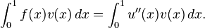
Conversely, if u with u(0) = u(1) = 0 satisfies (1) for every smooth function v(x) then one may show that this u will solve P1. The proof is easier for twice continuously differentiable u (mean value theorem), but may be proved in a distributional sense as well.
By using integration by parts on the right-hand-side of (1), we obtain
(2)

where we have used the assumption that v(0) = v(1) = 0.
A proof outline of existence and uniqueness of the solution
We can loosely think of to be the absolutely continuous functions of (0,1) that are 0 at x = 0 and x = 1 (see Sobolev spaces). Such function are (weakly) "once differentiable" and it turns out that the symmetric bilinear map
  then defines an inner product which turns into a Hilbert space (a detailed proof is nontrivial.) On the other hand, the left-hand-side
  is also an inner product, this time on the Lp space L2(0,1). An application of the Riesz representation theorem for Hilbert spaces shows that there is a unique u solving (2) and therefore P1. This solution is a-priori only a member of , but using elliptic regularity, will be smooth if f is.
The weak form of P2
If we integrate by parts using a form of Green's identities, we see that if u solves P2, then for any v,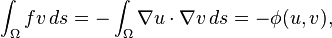
 denotes the gradient and
  denotes the dot product in the two-dimensional plane. Once more
  can be turned into an inner product on a suitable space
  of "once differentiable" functions of Ω that are zero on . We have also assumed that
  (see Sobolev spaces). Existence and uniqueness of the solution can also be shown.
Discretization
The basic idea is to replace the infinite dimensional linear problem:- Find
 such that
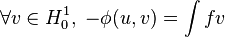
- (3) Find
 such that
 . There are many possible choices for V (one possibility leads to the spectral method). However, for the finite element method we take V to be a space of piecewise polynomial functions.
For problem P1, we take the interval (0,1), choose n values of x with 0 = x0 < x1 < ... < xn < xn + 1 = 1 and we define V by
![\begin{matrix} V=\{v:[0,1] \rightarrow \Bbb R\;: v\mbox{ is continuous, }v|_{[x_k,x_{k+1}]} \mbox{ is linear for }\\
k=0,...,n \mbox{, and } v(0)=v(1)=0 \} \end{matrix}](http://upload.wikimedia.org/math/b/7/2/b72d09847256eafb07a09abcd50969da.png)
 |
A function in  with zero values at the endpoints (blue), and a piecewise linear approximation (red) with zero values at the endpoints (blue), and a piecewise linear approximation (red) |
 then the derivative is typically not defined at any x = xk, k = 1,...,n. However, the derivative exists at every other value of x and one can use this derivative for the purpose of integration by parts.
 |
| A piecewise linear function in two dimensions. |
 |
| Basis functions vk (blue) and a linear combination of them, which is piecewise linear (red) |
One often reads Vh instead of V in the literature. The reason is that one hopes that as the underlying triangular grid becomes finer and finer, the solution of the discrete problem (3) will in some sense converge to the solution of the original boundary value problem P2. The triangulation is then indexed by a real valued parameter h > 0 which one takes to be very small. This parameter will be related to the size of the largest or average triangle in the triangulation. As we refine the triangulation, the space of piecewise linear functions V must also change with h, hence the notation Vh. Since we do not perform such an analysis, we will not use this notation.
Choosing a basis
 , i.e.,
![v_{k}(x)=\begin{cases} {x-x_{k-1} \over x_k\,-x_{k-1}} & \mbox{ if } x \in [x_{k-1},x_k], \\
{x_{k+1}\,-x \over x_{k+1}\,-x_k} & \mbox{ if } x \in [x_k,x_{k+1}], \\
0 & \mbox{ otherwise},\end{cases}](http://upload.wikimedia.org/math/8/0/7/807c9437f8c9ef8ef673c9583252901a.png) .
.Depending on the author, the word "element" in "finite element method" refers either to the triangles in the domain, the piecewise linear basis function, or both. So for instance, an author interested in curved domains might replace the triangles with curved primitives, and so might describe the elements as being curvilinear. On the other hand, some authors replace "piecewise linear" by "piecewise quadratic" or even "piecewise polynomial". The author might then say "higher order element" instead of "higher degree polynomial". Finite element method is not restricted to triangles (or tetrahedra in 3-d, or higher order simplexes in multidimensional spaces), but can be defined on quadrilateral subdomains (hexahedra, prisms, or pyramids in 3-d, and so on). Higher order shapes (curvilinear elements) can be defined with polynomial and even non-polynomial shapes (e.g. ellipse or circle).
Examples of methods that use higher degree piecewise polynomial basis functions are the hp-FEM and spectral FEM.
More advanced implementations (adaptive finite element methods) utilize a method to assess the quality of the results (based on error estimation theory) and modify the mesh during the solution aiming to achieve approximate solution within some bounds from the 'exact' solution of the continuum problem. Mesh adaptivity may utilize various techniques, the most popular are:
- moving nodes (r-adaptivity)
- refining (and unrefining) elements (h-adaptivity)
- changing order of base functions (p-adaptivity)
- combinations of the above (hp-adaptivity)
Small support of the basis
 |
Solving the two-dimensional problem uxx + uyy = − 4 in the disk centered at the origin and radius 1, with zero boundary conditions. (a) The triangulation. |
 |
| (b) The sparse matrix L of the discretized linear system |
 |
| (c) The computed solution, u(x,y) = 1 − x2 − y2. |


 in the (j,k) location is known as the Gramian matrix.) In the one dimensional case, the support of vk is the interval [xk − 1,xk + 1]. Hence, the integrands of and φ(vj,vk) are identically zero whenever | j − k | > 1.
Similarly, in the planar case, if xj and xk do not share an edge of the triangulation, then the integrals


Matrix form of the problem
If we write and
and  then problem (3), taking v(x) = vj(x) for j = 1,...,n, becomes
 for j = 1,...,n. (4)
 and
and  the column vectors (u1,...,un)t and (f1,...,fn)t, and if we let
- L = (Lij)
- M = (Mij)
- Lij = φ(vi,vj)

 . (5)
. (5)
. For a general function f(x), problem (3) with v(x) = vj(x) for j = 1,...,n becomes actually simpler, since no matrix M is used, , (6)
, (6)
 and
and  for j = 1,...,n.
As we have discussed before, most of the entries of L and M are zero because the basis functions vk have small support. So we now have to solve a linear system in the unknown
where most of the entries of the matrix L, which we need to invert, are zero.Such matrices are known as sparse matrices, and there are efficient solvers for such problems (much more efficient than actually inverting the matrix.) In addition, L is symmetric and positive definite, so a technique such as the conjugate gradient method is favored. For problems that are not too large, sparse LU decompositions and Cholesky decompositions still work well. For instance, Matlab's backslash operator (which uses sparse LU, sparse Cholesky, and other factorization methods) can be sufficient for meshes with a hundred thousand vertices.
The matrix L is usually referred to as the stiffness matrix, while the matrix M is dubbed the mass matrix.
General form of the finite element method
In general, the finite element method is characterized by the following process.- One chooses a grid for Ω. In the preceding treatment, the grid consisted of triangles, but one can also use squares or curvilinear polygons.
- Then, one chooses basis functions. In our discussion, we used piecewise linear basis functions, but it is also common to use piecewise polynomial basis functions.
Another consideration is the relation of the finite dimensional space V to its infinite dimensional counterpart, in the examples above
. A conforming element method is one in which the space V is a subspace of the element space for the continuous problem. The example above is such a method. If this condition is not satisfied, we obtain a nonconforming element method, an example of which is the space of piecewise linear functions over the mesh which are continuous at each edge midpoint. Since these functions are in general discontinuous along the edges, this finite dimensional space is not a subspace of the original .Typically, one has an algorithm for taking a given mesh and subdividing it. If the main method for increasing precision is to subdivide the mesh, one has an h-method (h is customarily the diameter of the largest element in the mesh.) In this manner, if one shows that the error with a grid h is bounded above by Chp, for some
 and p > 0, then one has an order p method. Under certain hypotheses (for instance, if the domain is convex), a piecewise polynomial of order d method will have an error of order p = d + 1.
If instead of making h smaller, one increases the degree of the polynomials used in the basis function, one has a p-method. If one combines these two refinement types, one obtains an hp-method (hp-FEM). In the hp-FEM, the polynomial degrees can vary from element to element. High order methods with large uniform p are called spectral finite element methods (SFEM). These are not to be confused with spectral methods.
For vector partial differential equations, the basis functions may take values in
 .
.Biomechanics
Biomechanics is the application of mechanical principles to biological systems, such as humans, animals, plants, organs, and cells. Perhaps one of the best definitions was provided by Herbert Hatze in 1974: "Biomechanics is the study of the structure and function of biological systems by means of the methods of mechanics". The word biomechanics developed during the early 1970s, describing the application of engineering mechanics to biological and medical systems. In Modern Greek, the corresponding term is εμβιομηχανική.
Biomechanics is closely related to engineering, because it often uses traditional engineering sciences to analyse biological systems. Some simple applications of Newtonian mechanics and/or materials sciences can supply correct approximations to the mechanics of many biological systems. Applied mechanics, most notably mechanical engineering disciplines such as continuum mechanics, mechanism analysis, structural analysis, kinematics and dynamics play prominent roles in the study of biomechanics.
Usually biological system are more complex than man-built systems. Numerical methods are hence applied in almost every biomechanical study. Research is done in a iterative process of hypothesis and verification, including several steps of modeling, computer simulation and experimental measurements.
Applications
The study of biomechanics ranges from the inner workings of a cell to the movement and development of limbs, to the mechanical properties of soft tissue, and bones. As we develop a greater understanding of the physiological behavior of living tissues, researchers are able to advance the field of tissue engineering, as well as develop improved treatments for a wide array of pathologies.
Biomechanics is also applied to studying human musculoskeletal systems. Such research utilizes force platforms to study human ground reaction forces and infrared videography to capture the trajectories of markers attached to the human body to study human 3D motion. Research also applies electromyography (EMG) system to study the muscle activation. By this, it is feasible to investigate the muscle responses to the external forces as well as perturbations.
Biomechanics is widely used in orthopedic industry to design orthopedic implants for human joints, dental parts, external fixations and other medical purposes. Biotribology is a very important part of it. It is a study of the performance and function of biomaterials used for orthopedic implants. It plays a vital role to improve the design and produce successful biomaterials for medical and clinical purposes.